Rockwell Automation Publication 750-AT006D-EN-P - January 2022 81
Chapter 6
Active Front End Tuning
The Active Front End (AFE) power converters in the PowerFlex 755T product family provide regenerative capability, unity power factor,
reduced input total harmonic distortion (THD), and reactive power compensation. In some applications, the power converter can be
integrated with the inverter using PowerFlex 755TL and PowerFlex 755TR drives. In other applications, the power converter is used as a bus
supply using PowerFlex 755TM drives, where external loads can be connected to the DC terminals.
Function
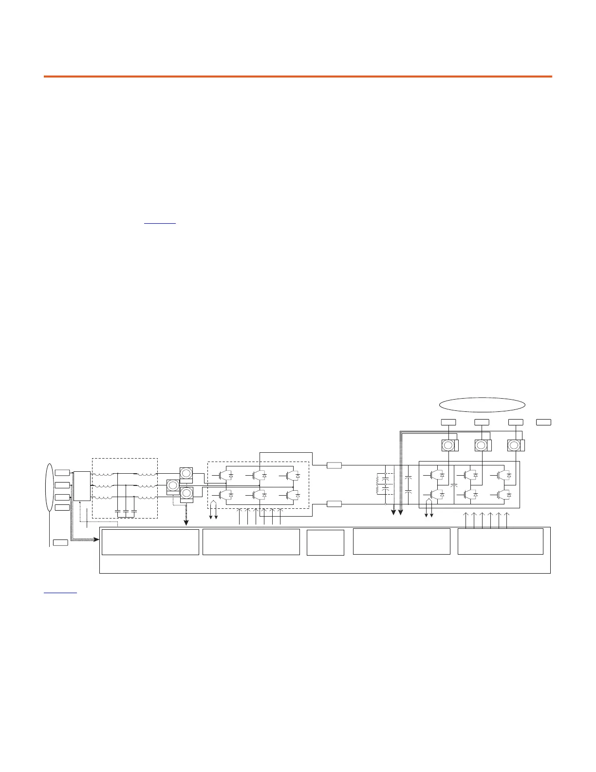
The AFE topology, shown in Figure 71, typically uses an LCL filter to reduce higher-order harmonics that result from the switching action of
the power converter. The interaction between the LCL filter and AFE control can cause a resonance condition, especially at relatively higher
bandwidth operation or in soft line conditions. Resonance can also occur due to interaction between the LCL filter and other nonlinear loads
connected to the same feeder. One solution involves detuning the control system. However, it reduces the dynamic performance of the
system.
In general, the AFE has an inner current control loop and an outer voltage control loop. This is analogous to torque and speed loops in motor
control. The voltage control loop usually has a lower bandwidth than the current control loop. The voltage control loop is responsible for
regulating the DC bus to a value higher than the peak value of the line voltage. This control loop generates the command to the q-axis
current control loop that represents either an absorbed or regenerated power. The d-axis current control loop is responsible for reactive
power control, which means that the AFE converter can operate as a reactive power compensator, provided that the total current supplied by
the converter does not exceed the converter rating. The q-axis current reference, the d-axis current reference, and the grid line voltage are
processed through the LCL steady-state compensation block and the power limiting function to generate the final q-axis and d-axis current
commands.
Figure 71 - Standard Regenerative Motor-Drive System Schematic
Figure 72
shows a simplified block diagram of the AFE control structure. The pulse-width modulation (PWM) that is used in the AFE is very
similar to the modulator used for inverter control, where eight switching states are available, including two zero states and six active states.
These power converters are commonly connected to the grid through an LCL filter that is responsible for filtering out higher-order
harmonics associated with the switching action of the power converter.
V
L1
, V
L2
, V
L3
Input Filter
I
a
, I
b
, I
c
I
a
, I
b
, I
c
V
DC
ISENSE
ISENSE
ISENSE
PE
PE
TB1-3
T/L 3
TB1-1
R/L1
S/L2
TB1-2
Three-phase
AC Input
Source
Ground
Source
Power Shield
Pre-charge
circuit
ISENSE
ISENSE
ISENSE
PE
Common Bus
Power Connecons
IGBT-based
Recfier—Secon
NTC
NTC
TB1-8
U/M1
TB1-9
V/M2
TB1-10
W/M3
TB1-7
DC-
TB1-6
DC+
LCL Filter
CPU and Control
Inverter Gate Drive Circuit
SMPS
Inverter Gate Drive Circuit
Line Currents, DC Bus, and
Temperature Measurements
Line Currents, DC Bus, and
Temperature Measurements/
Pre-charge Relay Control
Three-phase AC Output
Motor Shield
Inverter IGBT
Secon
PM
 Loading...


