Rockwell Automation Publication 750-AT006D-EN-P - January 2022 87
Chapter 6 Active Front End Tuning
DC Bus Observer
Basic concepts
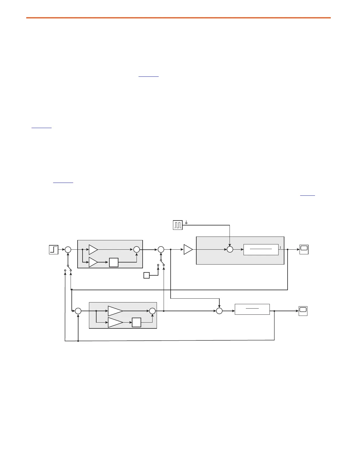
In 755TM bus supply applications, the measured instantaneous power on the inverter side is not available. Therefore, the DC Bus observer is
designed to estimate the load on the DC side of the power converter in real time. This estimated load is then fed back to cancel the effect of
the actual load, as shown in the simplified model in Figure 73
. This forces the plant to behave consistently, which makes it easier to achieve
and control higher performance levels. The DC Bus observer relies on processing the error difference between the measured DC bus voltage
and an estimated DC bus voltage through a PI controller. The deviation between the measured and the estimated DC bus values are mainly
due to external disturbances, such as load changes, or parameter variations, such as a fluctuation in DC bus capacitance. This occurs in
common DC bus applications where loads are being frequently connected to and disconnected from the DC bus. The system can be
configured to use either the measured DC bus voltage or the DC bus voltage estimated by the observer as the feedback signal for the voltage
control loop. The estimated DC bus current is displayed in real time for the purpose of load monitoring; see 13:325 [BusObs Curr Est].
In Figure 73
, notice that the current regulator B
W
is usually set 5 to 10 times higher than the voltage regulator B
W
. Consequently, the dynamics
of the current regulator can be ignored, and it can be represented by a unity again. The total capacitance of the system (C) is defined as the
summation of the internal capacitance (C
int
) and the external capacitance (C
ext
). The bus observer can automatically compensate for external
capacitance that is less than four times the internal capacitance of the drive
.
The DC bus observer uses an ideal model of the system with a feedback loop to estimate the disturbance, which represents any difference
between the real model and the actual system, including C
ext
, load changes, parameter variation, and so on.
As shown in Figure 73
, the algorithm consists of two interactive control loops; a standard DC bus voltage regulator, which is mainly
responsible for reference tracking, and the DC bus observer, which is mainly responsible for disturbance rejection. The system can be
configured to use the measured DC bus voltage or the estimated DC bus as a feedback signal for the voltage control loop. See Tuning
for
more information.
Figure 73 - Simplified Functional Block Diagram for DC Bus Observer
+
-
+
-
+
+
+
-
+
+
+
+
+
+
0
V DC
REF
I
q
VbusObsReg
Iq_Load_Est
VbusReg
Iq_Load
+
1
V DC
Power converter
Plant-Bus Capacitance
Inial Bus Capacitance
1
C
INT
• s
Vdc_Est
CurrentLoop
1
(C
INT
+ C
EXT
)s
1
—
s
1
—
s
K
P
K
I
K
POBS
K
IOBS
 Loading...


