Rockwell Automation Publication 750-AT006D-EN-P - January 2022 55
Chapter 3
Out-of-Box Tuning
In this chapter, the Gain Calculation section describes how gains are calculated out-of-box and when the drive updates parameters. The
Recommended Default Settings on page 58 describes how to configure a new drive. This out-of-box tuning method often yields satisfactory
performance where no further tuning intervention is required.
In this chapter, the drive settings for out-of-box tuning in Encoderless mode (10:1000 [Pri Vel Fb Sel] = 10:1048 [Open Loop Fb] or
10:1006 [Alt VelFb Sel] = 10:1048 [Open Loop Fb]) for velocity control are also provided. Encoderless mode is not available for position control.
Gain Calculation
The term out-of-box refers to default control loop gain settings that are pre-configured in a new drive. Because the load is unknown at this
point, the motor is assumed to be unloaded, the load ratio R = 0, and the load coupling is compliant. This value also applies to when the load
is known to be compliant. This chapter pertains to when the load ratio R = 0.
However, when the load is known or an autotune total inertia test has been performed to determine the load ratio, the control loop gains are
configured for a load ratio R > 0, and the load coupling is rigid. See Auto Tuning
on page 63 for more information.
These settings are the primary difference affecting out-of-box and autotune rules. Thus, the term out-of-box implies a compliant load with
R = 0 and the term autotune implies a rigid load with R > 0.
In a new drive configuration or when the load is unknown, 10:901 [Load Ratio] = 0, but the actual load ratio R > 0. As a result, the torque scaler
is lower than what is required and it must increase by a factor of R+1.
This load disconnect has the following effects:
• The effectiveness of acceleration feed forward reduces by a factor of R+1.
• The torque scaler borrows a factor of R+1 from K
VP
, lowering the actual velocity loop bandwidth by a factor of R+1 relative to the
[VReg Kp] that is applied to the control loops. Reducing K
VP
causes the spacing between it and K
VI
to become smaller, which reduces
the velocity-loop-damping that is associated with K
VI
. Reducing K
VP
also causes the loop spacing between K
VP
and K
PP
to become
smaller, which reduces the position-loop-damping that is associated with this reduction in loop spacing.
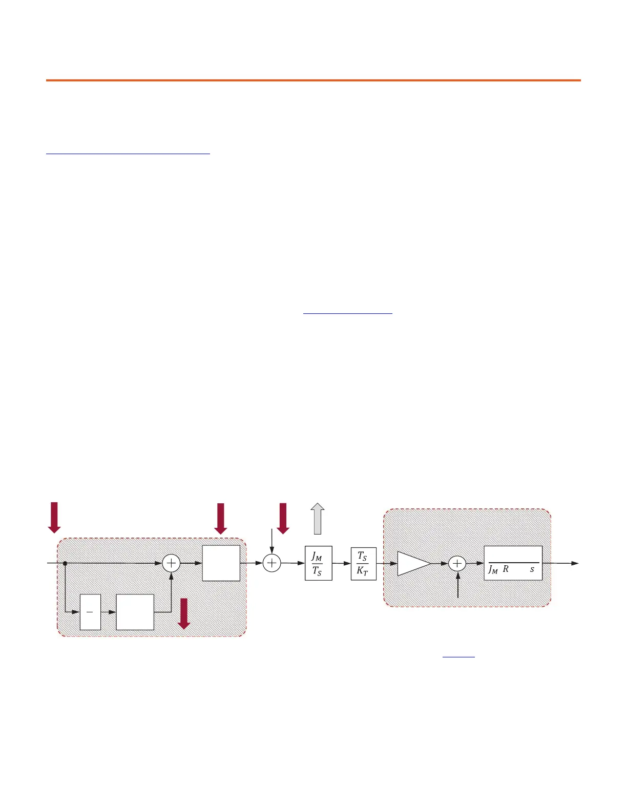
Figure 55 - Effects of Unknown Load R = 0
Variables that are relevant to increasing damping when K
VP
is artificially lowered include those listed in Table 20.
Velocity Loop
VP
S
K2
VP
S K2
s
1
Torque
Scalar (
K
J
)
K
AFF
R+1
Actual Velocity
Loop BW
Integrator
Damping
Loop Spacing
Damping
1
( +1)
2
K
T
Motor and
Load
Mechanics
Motor
Electrical
Load
Torque
System Under Control
Motor
Position
 Loading...


