Rockwell Automation Publication 750-AT006D-EN-P - January 2022 51
Chapter 2 Product Features
Low Pass Filters
Low pass filters are represented by the following first order transfer function, where F is the filter bandwidth in units of [Hz].
The filter is disabled when F = 0 Hz.
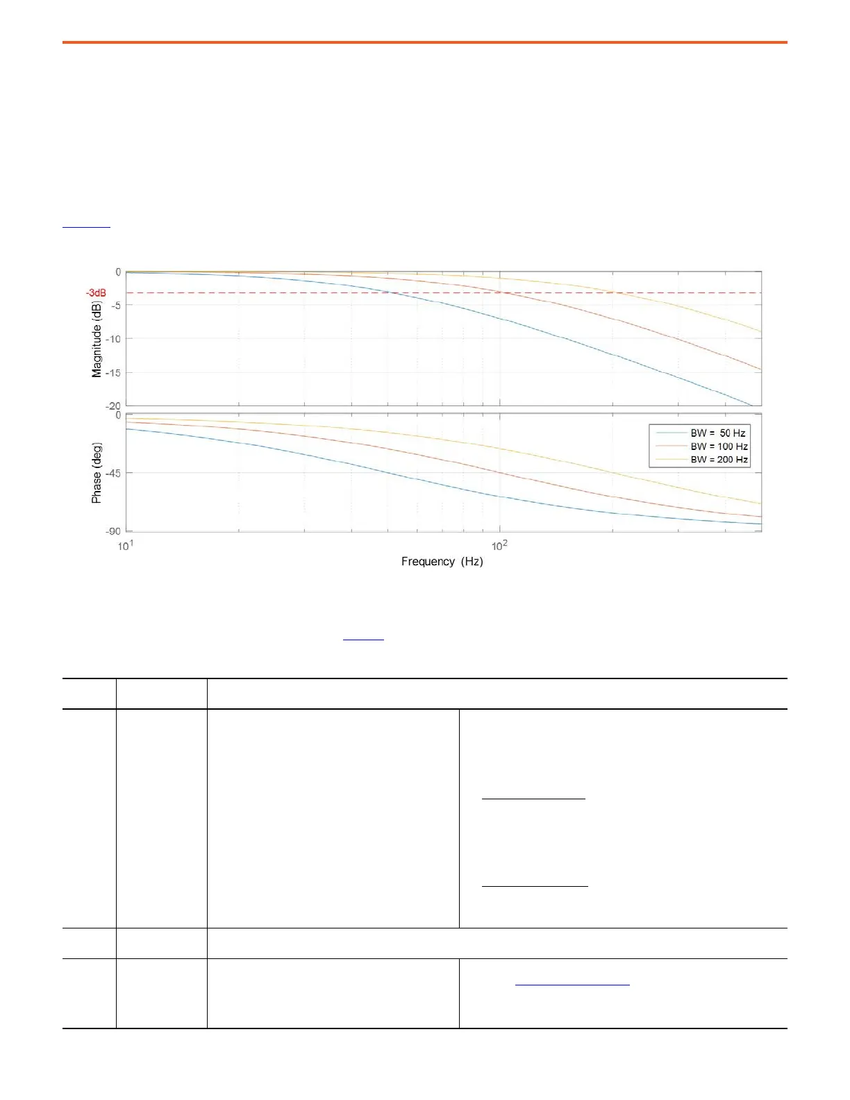
These filters pass low frequency signals, but attenuate frequencies above F. Bode plots with differing bandwidth settings are shown in
Figure 52
.
Figure 52 - First Order Low Pass Filter
The signal is attenuated 3 dB at the filter bandwidth F, also known as the cutoff frequency. The signal is attenuated 20 dB/decade beyond
the cutoff frequency.
Corresponding low pass filter parameters are given in Table 19
.
Table 19 - Low Pass Filter Parameters
Parameter
No.
Parameter Name Description
10:1002 [c Vel Fb LPF BW]
An automatically calculated value for the primary velocity
feedback low pass filter bandwidth. This parameter is
applied to the drive when 10:905 [System C/U Select] =
Calculated (0). It is calculated as a function of the
following parameters and it affects the DMTC and 10:906
[System BW] values.
• 10:407 [Motor Poles] – This parameter is the number of motor poles (p). It
is calculated as follows:
p = round (120 x [Motor NP Hertz] / [Motor NP RPM])
• Primary Encoder Resolution – The total resolution in edge counts per
revolution (EPR) is specified by parameters on the primary feedback
option card.
– Low-Resolution Example
: Resolution = 1024 pulses per revolution * 4
quadrature edge counts per pulse = 4096 EPR (12-bit). The low-
resolution PPR comes directly from a parameter on the option card.
When both A and B channels are selected for an incremental encoder,
the edge count multiplier is 4. This value is the typical and default
setting. When only channel A is selected, then the edge count multiplier
is 2.
– High-Resolution Example: Resolution = 1024 pulses per revolution *
1024 edge counts per pulse = 1,048,576 EPR (20-bit). For high-resolution
devices, the overall resolution choices are 20-bit default or an optional
24-bit when the corresponding configuration bit is selected.
10:1003 [u Vel Fb LPF BW]
Sets the primary velocity feedback low pass filter bandwidth.
It is applied to the drive when 10:905 [System C/U Select] = User Entered (1)
10:1004 [c Vel Fb LPF Gn]
Displays the calculated value of the primary velocity
feedback filter gain. This gain value is applied when
parameter 10:905 [System C/U Sel] is set to 'Calculated'
(0). The 'calculated' filter gain is always zero.
• Because this is a Lead Lag Filter, a filter gain of zero will configure the
filter as a Low Pass Filters
on page 51.
• This filter determines the amount of filtering applied to the primary
velocity feedback channel and is only active in Flux Vector motor control
modes.
Gs
2
F
s 2
F+
-----------------------=
 Loading...


