d05786.fm
INSTALLATION MANUAL
BRP-Powertrain
Effectivity: 912 i Series
Edition 1/Rev. 2
76-00-00
Page 9
January 01/2014
Graphic
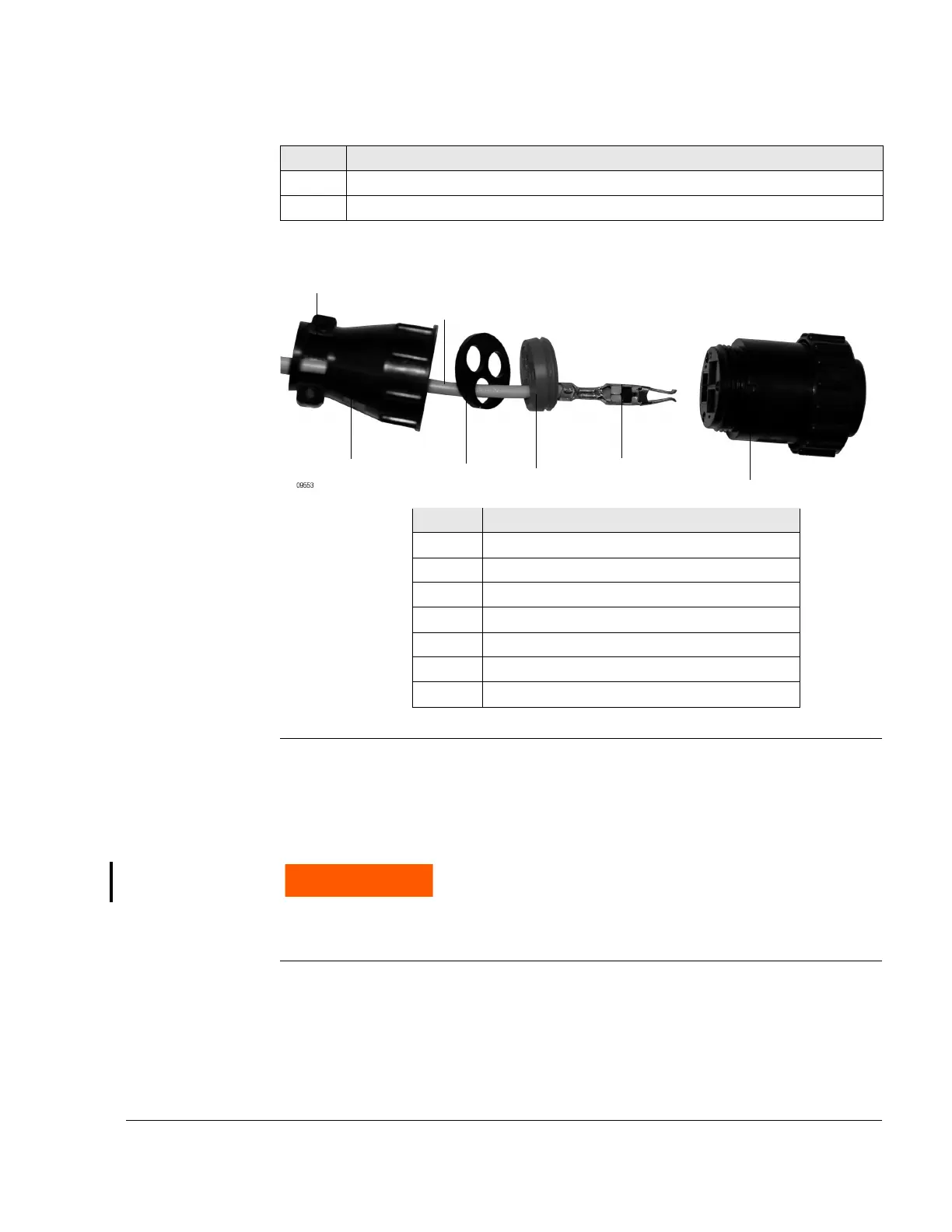
Fitting the AMP connector
Fig. 5
2.4) Installation position of the FUSE BOX assy.
The FUSE BOX must be placed that the maximum permissible compo-
nent temperature must not exceed.
Temperature Permissible component temperature: Max. +80 °C (176 °F)
5 Check for tight fit.
6 Install strain relief clamp (4).
Step Procedure
Part Function
1Line
2 Socket contact
3 Connector
4 Strain relief clamp
5 Connector receptacle
6 Squeeze plate
7 Cable holder
The FUSE BOX must not be installed in the cockpit.
Installation in the engine compartment ONLY!
 Loading...


