d05787.fm
INSTALLATION MANUAL
BRP-Powertrain
Effectivity: 912 i Series
Edition 1/Rev. 2
78-00-00
Page 9
January 01/2014
4) Dimensions of the exhaust system
4.1) Exhaust system assy.
See Fig. 4 und Fig. 5.
Location and po-
sition of the tem-
perature sensor
The axis of the temperature sensor may be inclined up to 75 ° from the
vertical, so that any residual water will not be collected in the tip of the
temperature sensor.
The sensor element itself has no particular orientation, it can be rotated
360° around the axis. The tip of the temperature sensor must be positi-
oned free in the gas flow.
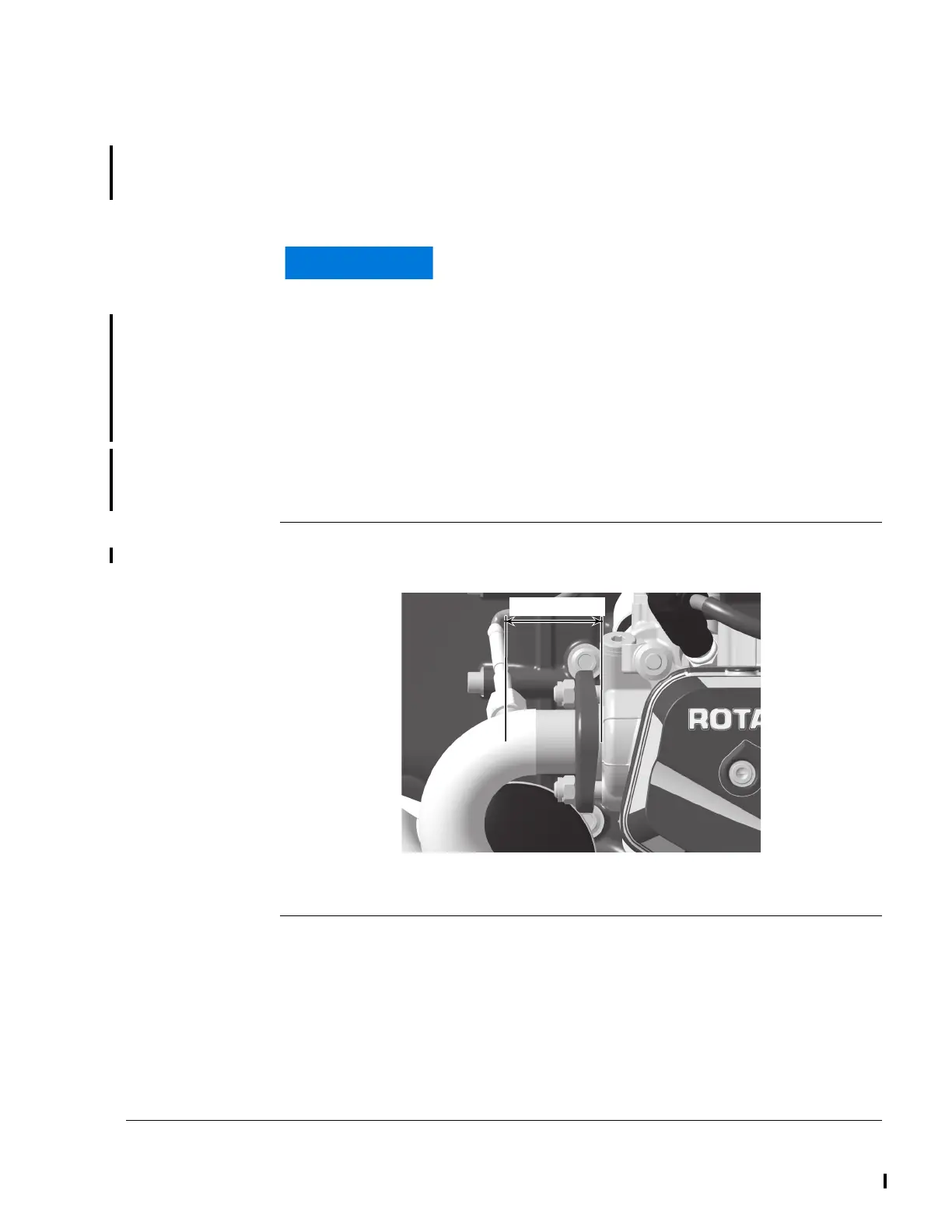
Position Approx. 50 mm (1.97 in.) from the cylinder head flange i.e. measured
from the flat surface on the cylinder head to encoder axis. It is important
that all 4 temperature sensors are placed at the same distance!
Graphic Position
Fig. 4
If the EGT sensor is fitted on a slope or with the sen-
sor tip pointing upwards, then various fluids can lead
to undesired corrosion. The sensor could then fail.
~ 50 mm/~ 1.97 in.~ 50 mm/~ 1.97 in.
06592
 Loading...


