d05781.fm
INSTALLATION MANUAL
BRP-Powertrain
Effectivity: 912 i Series
Edition 1/Rev. 2
24-00-00
Page 29
January 01/2014
5.4) Wiring diagram
General note EMS diagram see 24-00-00 page 31.
Wiring power side see 24-00-00 page 32.
Wiring HIC connector and warning lamps see 24-00-00 page 34.
Cable cross-sec-
tion
In general, the cable cross-sections have to correspond to the EMS dia-
gram.
Deviations For deviations from the recommended cross-sections the aircraft manu-
facturer is responsible.
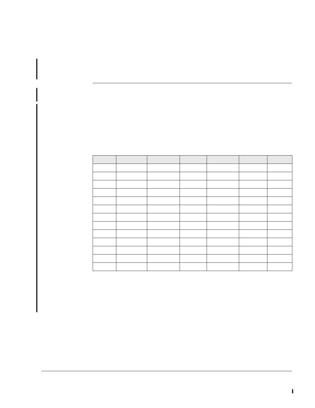
The minimum cable cross-section from the battery to the starter relay and
from there to the electric starter and for the ground line (start system)
depends on the cable length “I“(= Sum of the supply line and ground line
of the electric starter) and has to be calculated according to the following
table.
The internal resistance of the battery and the resistance of the electrical
system (wires, contact points, relay contacts) largely determine the per-
formance of the starting system. Therefore, the total loop resistance
(R
Smax
) may not exceed 0.015 Ω.
R
Smax
= Σ R = R
iBatt
+ R
C Starter relay
+R
L
+ R
Other
I [m] l [ft] A
min.
[mm
2
] A
min.
[in
2
] A
max.
[mm
2
] A
max.
[in
2
] AWG
min.
<4 <13 20.408 0.031 25 0.039 4
4<I<4.5 13<I<14.8 22.959 0.036 35 0.054 3
4.5<I<5 14.8<I<16.4 25.51 0.04 35 0.054 3
5<I<5.5 16.4<I<18 28.061 0.043 35 0.054 2
5.5<I<6 18<I<19.7 30.612 0.047 35 0.054 2
6<I<6.5 19.7<I<21.3 33.163 0.051 35 0.054 2
6.5<I<7 21.3<I<23 35.714 0.055 50 0.078 1
7<I<7.5 23<I<24.6 38.265 0.059 50 0.078 1
7.5<I<8 24.6<I<26.2 40.816 0.063 50 0.078 1
8<I<8.5 26.2<I<27.9 43.367 0.067 70 0.109 0
8.5<I<9 27.9<I<29.5 45.918 0.071 70 0.109 0
9<I<9.5 29.5<I<31.2 48.469 0.075 70 0.109 0
9.5<I<10 31.2<I<32.8 51.02 0.079 70 0.109 0
 Loading...


