d05398.fm
INSTALLATION MANUAL
BRP-Powertrain
Effectivity: 912 i Series
Edition 1/Rev. 0
79-00-00
Page 3
January 01/2012
1) Lubrication system (oil system)
1.1) System description
Drive See Fig. 2.
NOTE: The oil pump is driven by the camshaft.
The main oil pump sucks the engine oil from oil tank (1) via the oil cooler
(3) and forces it through the oil filter to the individual points of lubrication
(also lubricates the propeller governor).
The surplus oil emerging from the points of lubrication accumulates on
the bottom of the crankcase and is forced back to the oil tank by the
crankcase blow-by gases.
Purging NOTE: The oil circuit is vented via nipple in the oil tank.
Connections
Only the following connections need to be established to complete the
lubrication system (oil system).
NOTE: An oil tank is included with the standard engine version.
No provision has been made for attachment of an oil cool-
er on the engine.
Non-compliance can result in serious injuries or
death!
The oil cooler and its connections must be certified
according to the latest regulations, such as FAR and
EASA, by the aircraft or fuselage manufacturer.
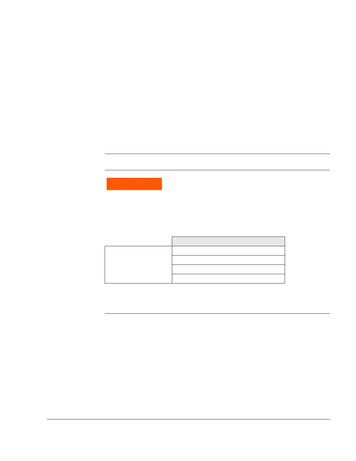
Oil circuit, engine (main oil pump)
Connections from
Oil tank (outlet) to oil cooler
Oil cooler to oil pump (inlet)
Oil return to oil tank (inlet)
Oil tank to purging line
 Loading...


