d05786.fm
INSTALLATION MANUAL
BRP-Powertrain
Effectivity: 912 i Series
Edition 1/Rev. 2
76-00-00
Page 13
January 01/2014
5) Display
Indicating instru-
ments
Only use display devices that have a CAN Aerospace interface. For
instruments and data of the CAN Aerospace protocol, contact an autho-
rized distributor- or Service Center for ROTAX aircraft engines.
NOTE: Only the defined operating limits by ROTAX (see latest
Operators Manual) are valid for engine operation. The re-
sponsibility for adapting these operating limits to the dis-
play accordingly is up to the display manufacturer .
5.1) Pin assignment of display interfaces
Display pin as-
signment
See Fig. 6.
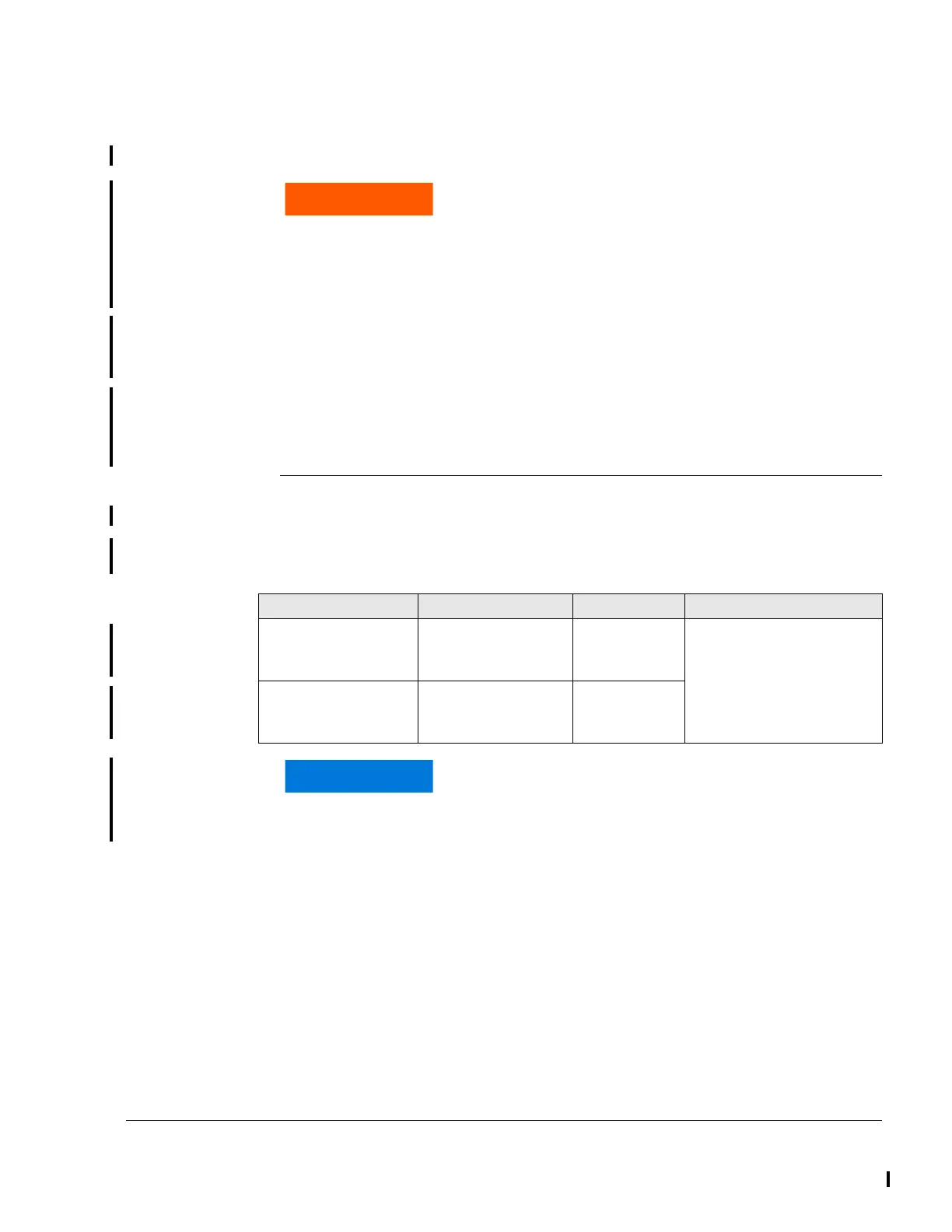
Pin assignment of display interfaces)
Non-compliance can result in serious injuries or death!
Only use display instruments, which have two separate
CAN Aerospace interfaces and can work separately.
The CAN Aerospace interfaces of LANE A and B must
not be connected, otherwise the redundancy of the dis-
play instrument is no longer given.
Pin Description HIC Pin no. Pin no. on display
LANE A Sub-D DE9
Display interface
CAN_LOW_1_A
CAN_GND_1_A
CAN-HIGH_1_A
5 (HIC A)
4 (HIC A)
6 (HIC A)
Refer to the connection
specifications of the display
manufacturer.
LANE B Sub-D DE9
Display interface
CAN_LOW_1_B
CAN_GND_1_B
CAN_HIGH_1_B
7 (HIC B)
6 (HIC B)
8 (HIC B)
In order to ensure a high electromagnetic compatibi-
lity in data transmission, twisted cables (3 pins:
CAN_H, CAN_L, CAN_GND) must be used for the
CAN-connections.
 Loading...


