d05781.fm
INSTALLATION MANUAL
BRP-Powertrain
Effectivity: 912 i Series
Edition 1/Rev. 2
24-00-00
Page 8
January 01/2014
Graphic
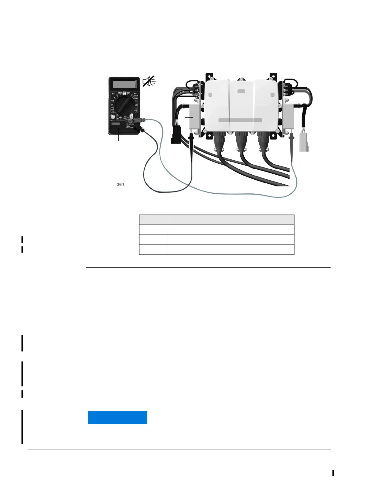
Continuity check
Fig. 1
2.1) Controller boards on the FUSE BOX
See Fig. 2 and Fig. 3.
The EMS grounding cables of the wiring harness (labelled: "Regulator A“
or cables with cable lugs) must be connected to the 3 attachment points of
the EMS ground. Each side of the FUSE BOX has three ground connec-
tions.
EMS ground has 3 interconnected ground connections which may be used
interchangeably.
Airframe ground, also has 3 interconnected ground connections which
may be used interchangeably, one of which must be connected to the air-
frame ground.
NOTE: Airframe ground is independent of EMS ground and must
NOT be interconnected.
Part Function
1Multimeter
2 Rectifier regulator A (black wire connector)
3 Rectifier regulator B (grey wire connector)
The tightening torque of the nuts to secure the EMS
grounding cables and the airframe ground of the re-
spective attachment points must be 1.2 Nm
(10.7 in.lb).
 Loading...


