d05782.fm
INSTALLATION MANUAL
BRP-Powertrain
Effectivity: 912 i Series
Edition 1/Rev. 2
61-00-00
Page 4
January 01/2014
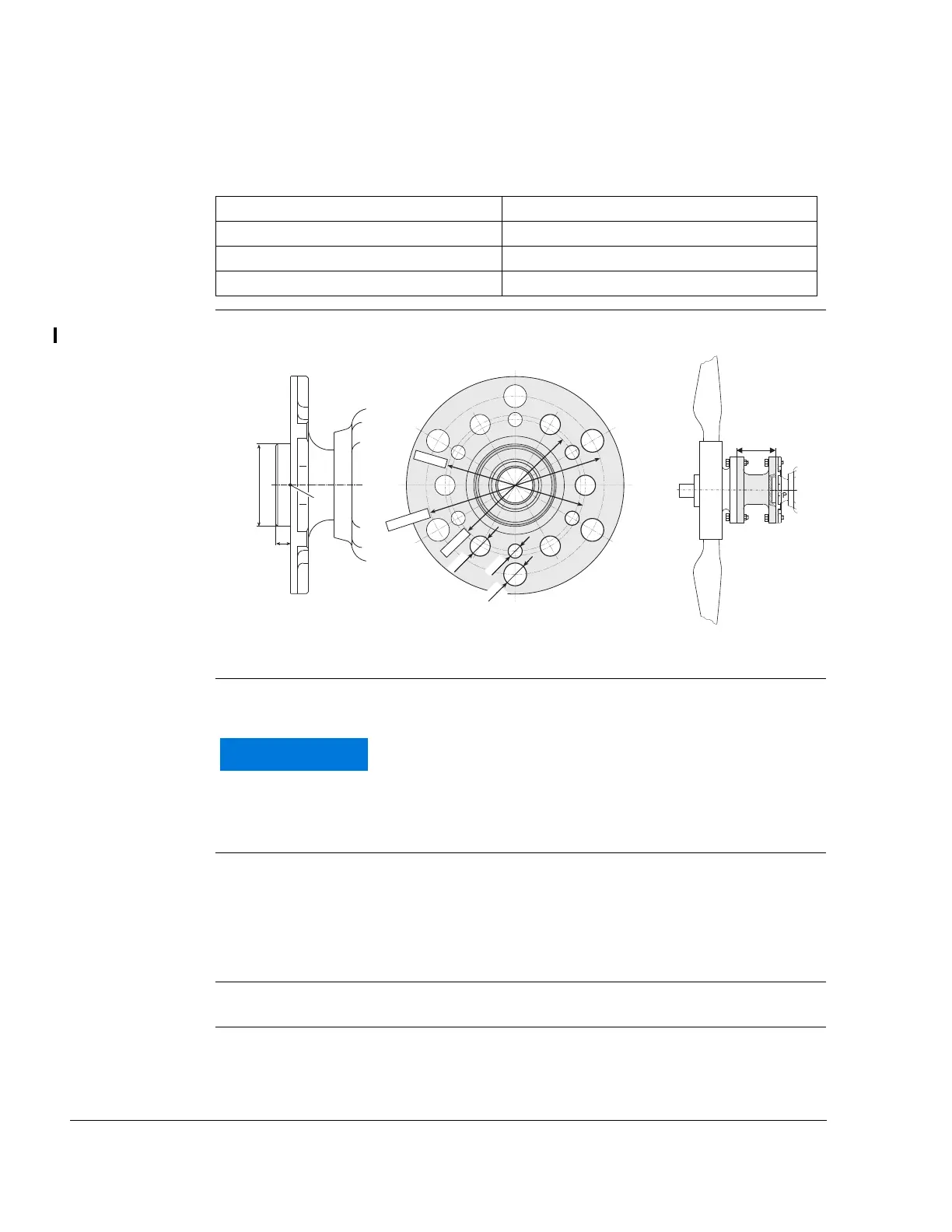
Propeller shaft
flange
See Fig. 2
Attachment of propeller on prop shaft flange:
Graphic Propeller shaft flange
Fig. 2 02581, 09193
1.2) Operating limits
Torque
Max. torque:
- 340 Nm (250.77 ft.lb.) (on propeller)
Max. moment of
inertia
Max. permissible moment of inertia on propeller:
- 6000 kgcm
2
(14.238 lb ft
2
)
- Normal between 1500 kg cm
2
and 6000 kg cm
2
(3.559 lb ft
2
and
14.238 lb/ft
2
)
Extension of
propeller shaft
- Max. extension of the propeller shaft: 120 mm (4.72 in.)
Out of balance Dynamic balancing of the propeller as specified by the propeller manufac-
turer must be carried out.
Pitch circle diameter 75 mm (2.95 in.) 6x through holes 8 mm (0.31 in.)
Pitch circle diameter 80 mm (3.15 in.) 6x through holes 11.5 mm (0.45 in.)
Pitch circle diameter 101.6 mm (4“) 6x through holes 13 mm (0.51 in.)
Hub diameter 47 mm (1.85 in.)
Lk = ø101,6
Lk = ø80
Lk = ø75
ø13,018
ø11,5
ø12,975
ø8
+0,2
8,5
P
ø47
-0,05
Modification of the propeller shaft is not permitted.
 Loading...


