d05787.fm
INSTALLATION MANUAL
BRP-Powertrain
Effectivity: 912 i Series
Edition 1/Rev. 2
78-00-00
Page 7
January 01/2014
3) Attaching the exhaust system
General note The shape and configuration of the exhaust system is essentially deter-
mined by the free space available in the aircraft.
Two M8x23 studs are provided on each cylinder for attaching the exhaust
system.
Location of the
studs
NOTE: All dimensions from zero reference point (P).
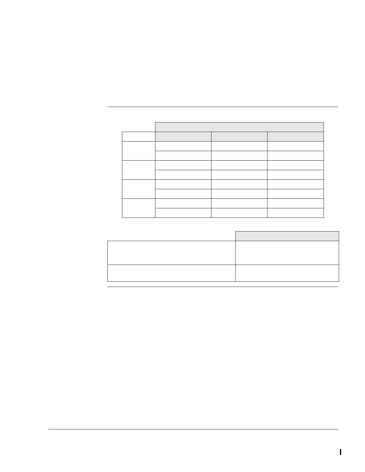
Coordinates
Location
x axis mm/in. y axis mm/in. z axis mm/in.
Cylinder 1 -160/-6.3 -196/-7.72 -82/-3.23
-160/-6.3 -212/-8.35 -113/-4.45
Cylinder 2 -192/-7.56 196/7.72 -82/-3.23
-192/-7.56 212/8.35 -113/-4.45
Cylinder 3 -408/-16.06 -196/-7.72 -82/-3.23
-408/-16.06 -212/-8.35 -113/-4.45
Cylinder 4 -438/-17.24 196/7.72 -82/-3.23
-438/-17.24 212/8.35 -113/-4.45
Attachment points
Max. permissible forces (safe load) in (N/lb-
force)
on x, y and z axis
1000/224.81
Max. permissible bending moment (safe load)
in (Nm/ft.lb) on x, y and z axis
40/30
 Loading...


