d05781.fm
INSTALLATION MANUAL
BRP-Powertrain
Effectivity: 912 i Series
Edition 1/Rev. 2
24-00-00
Page 11
January 01/2014
3) Technical data and connection of the electric components
3.1) Internal generator
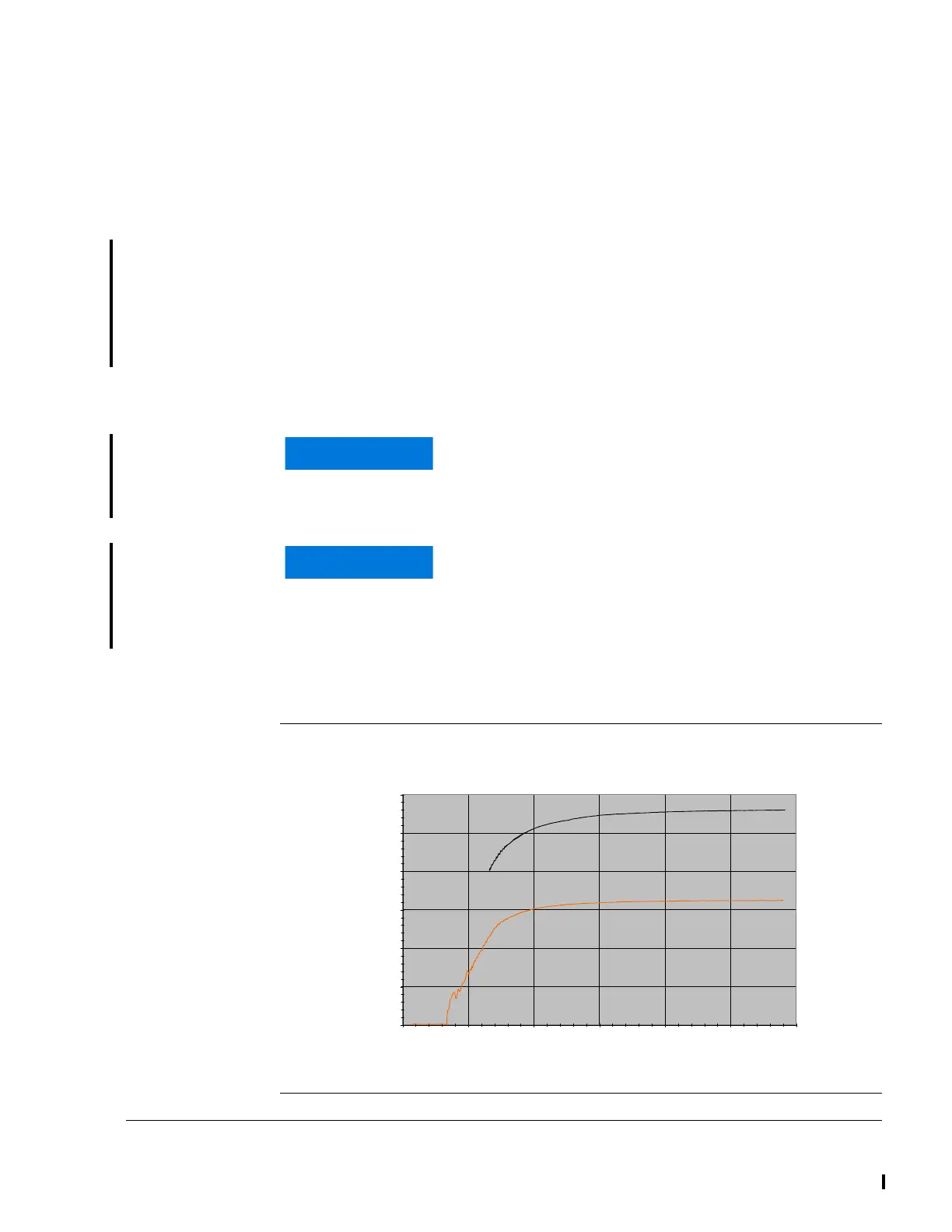
General note See Fig. 4.
The internal generator has two isolated coils integrated (individual gener-
ators). During the starting operation, the EMS system is powered by the
battery. With sufficient speed generator B takes over this function. After
the EMS system check, generator A takes over the supply of the EMS
system (engine), if the switching threshold is exceeded. Generator B is
then used to supply the aircraft instruments and for charging the battery.
- Generator A 14.2 V/16 A (220 W nominal capacity at 20°C/68 °F)
- Generator B 14.2 V/30 A (420 W nominal capacity at 20°C/68 °F)
For monitoring the battery voltage and to ensure that the battery is char-
ged, a voltmeter and ammeter is necessary.
Graphic Performance diagram showing engine speed against amps
Fig. 4
06591
If generator A fails, generator B takes over its func-
tions. The onboard computer and the instruments will
be supplied by the battery. The battery will no longer
be charged!
If generator B fails, the battery will no longer be
charged. The engine still runs on generator A and the
instruments will be supplied by the battery. The func-
tion of the instruments depends on the state of charge
of the battery.
Stator 912 iS
0,00
5,00
10,00
15,00
20,00
25,00
30,00
0 1000 2000 3000 4000 5000 6000
Engine Speed [rpm]
Curren [A]
Generator B
Generator A
 Loading...


