Engineering manual - SAB 193-233-283 S A-frame (including ATEX)
126/175
008831 en 2022.02
Installation instructions
Compressor/motor coupling installation
The unit has compressor to motor alignment through the use of a machined cast iron tunnel.
This tunnel is factory-set through machining tolerances ensuring motor/compressor alignment.
No alignment is required in the field. See Fig. 83.
7.27 BPU coupling installation procedure
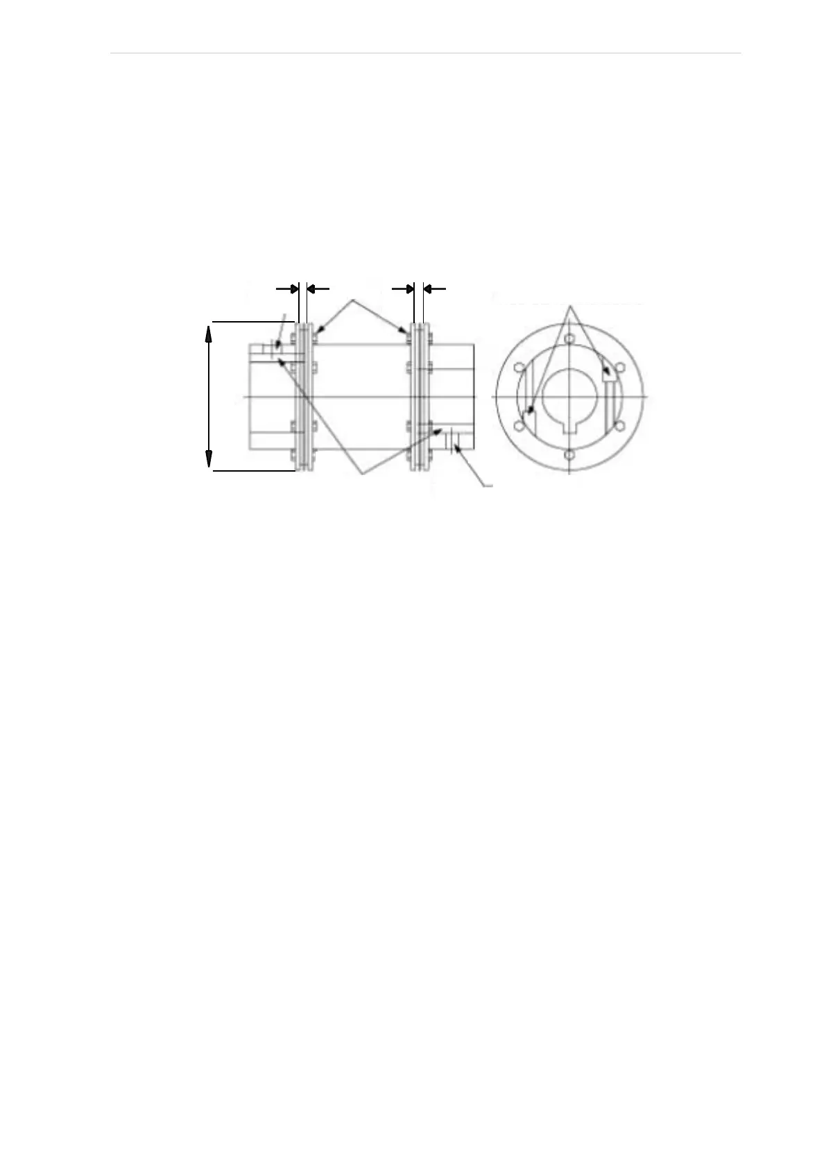
Fig. 83
1. Inspect shafts and hubs to make sure they are free from burrs.
2. Fit the key to the shaft.
Note: Never tighten the clamp bolts without the hub mounted onto the appropriately sized
shaft. Also, do not tighten the set screw before the clamp bolts. Make sure it is not engaging
the top of the key before proceeding to step 3.
Apply a light oil film on all contact surfaces. Do not use any oil with molibdenum bisulphite
or high-pressure additives and do not use grease. These substances notably reduce the
friction coefficient.
3. With the clamp bolts loose and the set screw slightly unscrewed, install the motor and
compressor coupling hubs and key on their respective shafts.
4. Make sure they can slide horizontally so that once the disc packs are installed, no axial
stress is transferred to the disc packs by a stuck coupling hub.
5. Rotate both hubs so that the keys are 180 degrees opposite each other.
6. With the hubs mounted and the axial spacing set, proceed to place the spacer between
the two hub flanges. Be careful when handling the spacer.
Make sure the spacer is fully supported.
If the spacer is not fully supported, the unitised flex discs may be damaged after
installation.
7. Install the unitised flex disc now.
Make sure that all bolt threads are clean and lightly oiled.
8. Start a bolt through a bolt hole in the spacer.
Set
Disc pack
Hub clamping bolts
Set screw
Keyways located
180° opposite
lock nuts
screw
G G
A
 Loading...