Engineering manual - SAB 193-233-283 S A-frame (including ATEX)
76/175
008831 en 2022.02
Technical description
4.36 Instrumentation
The screw compressor unit can be controlled by the UniSAB III control system, which is
mounted on the unit and connected to a number of temperature and pressure sensors on the
unit.
The UniSAB III control system is described in a separate manual.
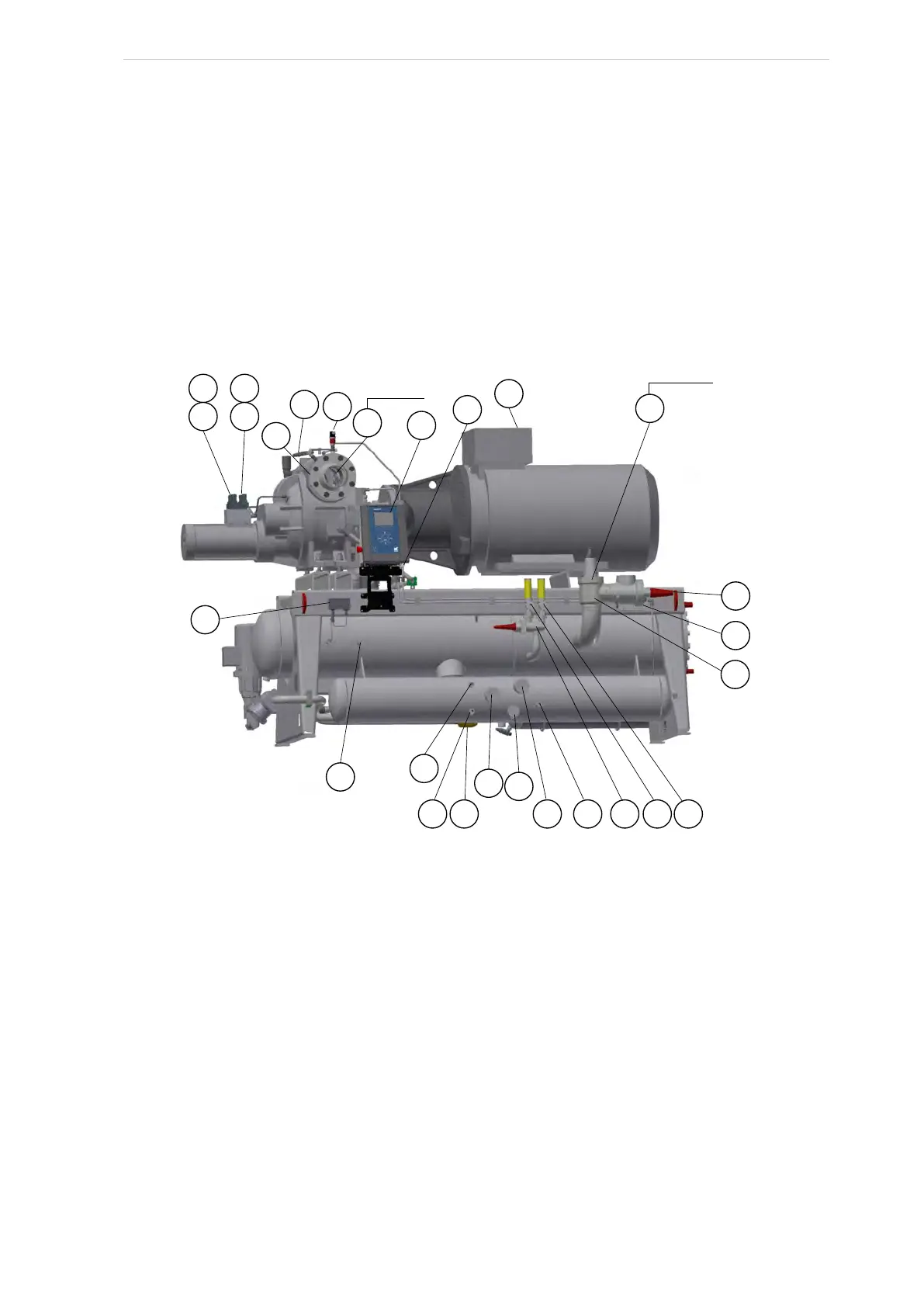
Fig. 53 and Fig. 54 show the positions of sensors, valves, etc.
See also the general piping diagram in subsection 4.34.
The numbers refer to the list in subsection 4.35 Key to piping diagram.
Fig. 53: Positions of valves and components SAB 193 with OHU 04123
181 183
182 184
151
158
114
101
EC
192
107
102
200
126
108
163
116
161
103
105
154 106
117
104
Not shown
152
Behind 126
160
159
 Loading...