Engineering manual - SAB 193-233-283 S A-frame (including ATEX)
008831 en 2022.02
61/175
Technical description
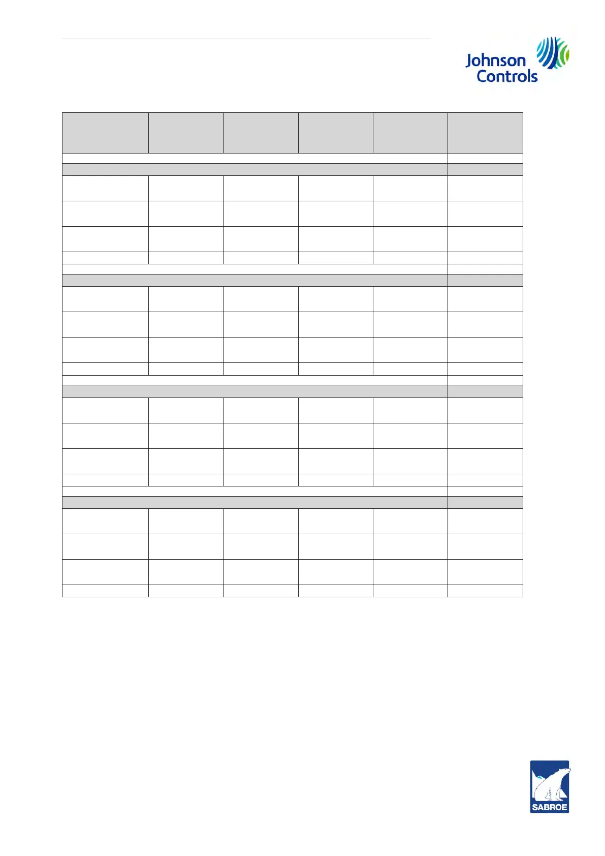
Unit
Model
Piping
line size
Pound
per min.
per 5 min.
Kg per min.
per 5 min.
Liquid
volume
cu ft
Liquid
volume
liter
R717 HS*
SAB 193 S and
L
3
/
4
75.5 34.2 2.1 59.4
SAB 233 S,
L and E
1 151.0 68.5 4.1 116.0
SAB 283 S,
L and E
1
1
/
4
219.5 99.6 6.0 169.8
SAB 283 X 1
1
/
4
300.0 136.2 8.2 232.0
R717 Booster*
SAB 193 S and
L
3
/
8
13.5 6.1 0.4 11.3
SAB 233 S,
L and E
1
/
2
25.5 11.5 0.7 19.8
SAB 283 S,
L and E
1
/
2
37.0 16.7 1.0 28.3
SAB 283 X
3
/
4
49.5 22.4 1.3 36.7
R507 HS*
SAB 193 S and
L
3
/
4
250.5 113.7 4.0 113.2
SAB 233 S,
L and E
1 500.5 227.2 8.1 229.2
SAB 283 S,
L and E
1
1
/
4
726.5 329.8 11.7 331.1
SAB 283 X 1
1
/
4
994.0 451.2 16.0 452.8
R507 Booster*
SAB 193 S and
L
3
/
8
41.5 18.8 0.7 19.8
SAB 233 S,
L and E
1
/
2
72.5 32.9 1.2 33.9
SAB 283 S,
L and E
1
/
2
106.5 48.3 1.7 48.1
SAB 283 X
3
/
4
146.0 65.8 2.3 65.0
Table 6: * Based on 100 ft liquid line. For longer runs, increase line size accordingly.
Conditions
Booster High-stage
Evaporating: -40°C [-40°F] Evaporating: -17.8°C [-17.8]
Condensing: +35°C [95°F] Condensing: +35°C [95°F].
Intermediate: -12.2°C [10°F]
4.29 Thermosyphon oil cooling
Thermosyphon oil coolers, like water (or glycol)-cooled oil coolers, eliminate the capacity and
power penalties associated with liquid injection oil cooling. Thermosyphon oil coolers have the
 Loading...