Engineering manual - SAB 193-233-283 S A-frame (including ATEX)
008831 en 2022.02
63/175
Technical description
Unit
Type of cooler Connection
Dia. Plates Inlet
Outlet
SAB 193 S, L High-stage 14 in. 116 3 in. 3 in.
SAB193 S, L and SAB
233 S, L, E
Booster 14 in. 66 2 in. 2 in.
SAB 233 S, L High-stage 14 in. 190 3 in. 3 in.
SAB 233 E
High-stage 14 in. 288 3 in. 4 in.
SAB 283 S, L Booster 24 in. 56 3 in. 3 in.
SAB 283 S, L High-stage 24 in. 136 4 in. 5 in.
SAB 283 E, X and
SAB 355 S, L
High-stage 24 in. 188 4 in. 5 in.
SAB 283 E, X and
SAB 355 S, L, E
Booster 24 in. 72 3 in. 3 in.
SAB 355 X Booster 24 in. 136 4 in. 5 in.
Table 8: Oil cooler data
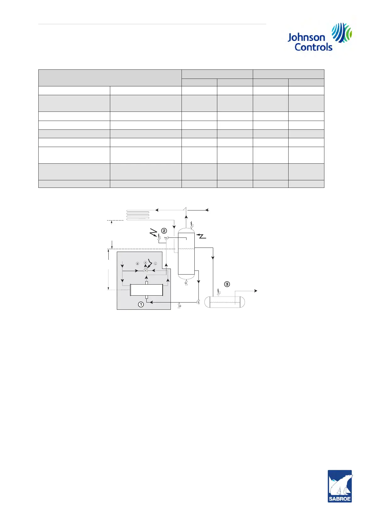
Fig. 37
1. The thermosyphon oil cooler is supplied with the oil side piped to the compressor unit and
stub ends supplied on the refrigerant side.
2. A refrigerant-side safety valve is required in this location only when refrigerant isolation
valves are installed between the cooler and thermosyphon receiver. If no valves are used be-
tween the cooler and TSOC receiver, the safety valve on the TSOC receiver must be sized to
handle the volume of both vessels. Then, the safety valve on the cooler vent (liquid refrigerant
side) can be eliminated.
3. The system receiver must be below the thermosyphon receiver in this arrangement.
4.30 Water-cooled oil cooling
The plate and shell or plate-and-shell type water-cooled oil cooler is mounted on the unit com-
plete with all oil piping. The customer must supply adequate water connections. Determine the
size of the water-cooled oil cooler supplied with the unit as outlined in COMP1. The water sup-
ply must be sufficient to meet the required flow.
Johnson Controls Denmark recommends a closed-loop system for the waterside of the oil
cooler. Careful attention to water treatment is essential to ensure adequate life of the cooler if
cooling tower water is used. It is imperative that the condition of cooling water and
System condenser
Vapour
Safety
v
alve
Static head
t
o overcome
condenser
pressure drop
Thermosyphon
r
eceiver
Liquid overflow
dr
ain to receiver
To system
e
vaporator
System
receiver
(Mounted below
thermosyphon r
eceiver level)
Liquid
le
vel
Oil temp.
c
ontrol valve
Hot
Cool
Cool
oil out
Refrigerant in
Refrigerant
Hot oil in
Plate cooler
T
SOC
6 ft.
(183 cm)
M
in.
out
 Loading...