Engineering manual - SAB 193-233-283 S A-frame (including ATEX)
008831 en 2022.02
99/175
Technical data
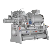
6.10 Direction of rotation
The direction of rotation of the compressor is clockwise when looking at the coupling flange
and the compressor as illustrated in Fig. 71.
Fig. 71: Direction of rotation
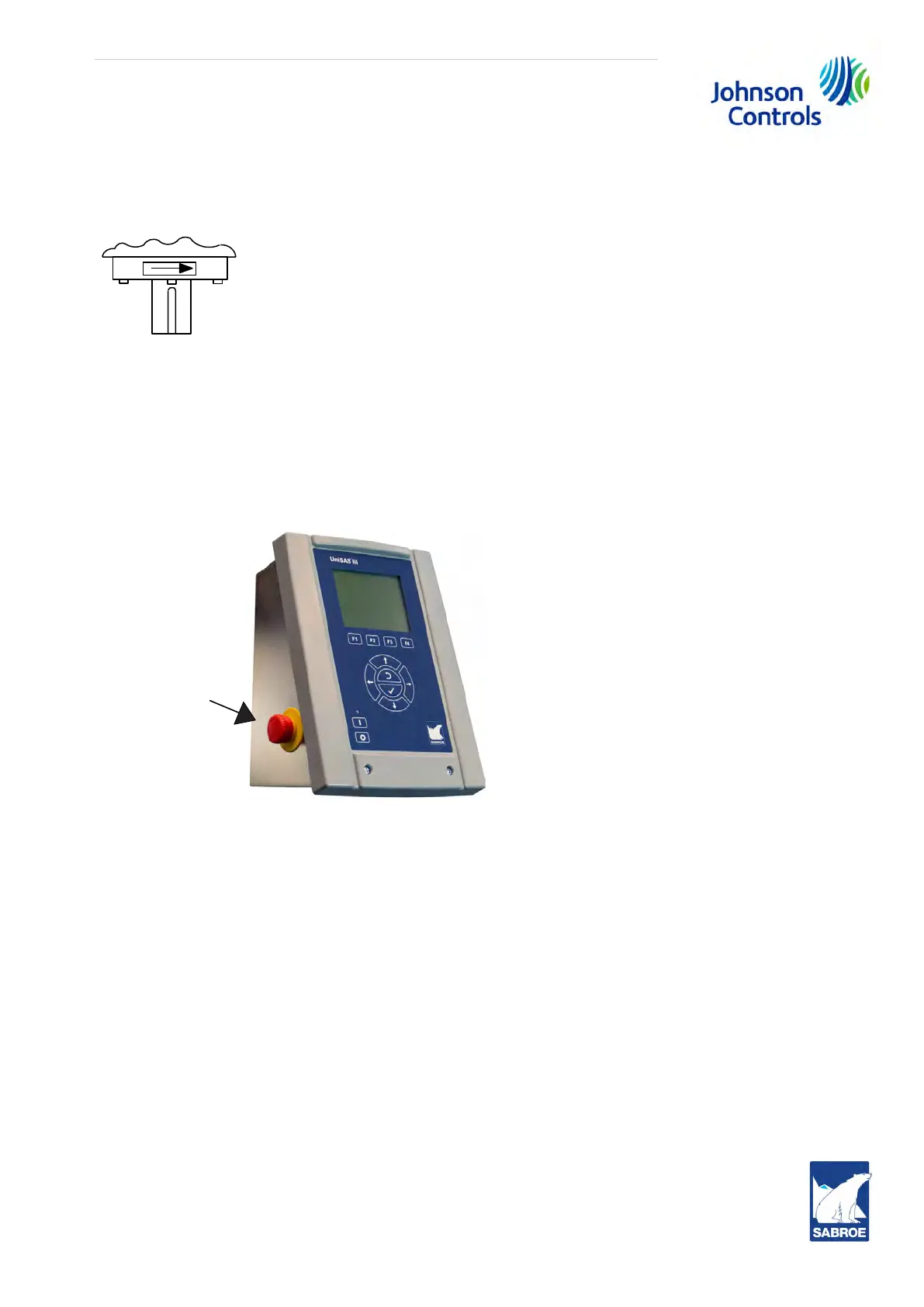
6.11 Emergency stop
The compressor control system must be equipped with an emergency stop.
If the compressor is supplied with a UniSAB III control system, this emergency stop will be an
integrated part of the system as shown in Fig. 72.
Fig. 72: Emergency stop on the unit
The emergency device must be adjusted in such a way that after a stop instruction it stays in
its stop position until it is deliberately reset.
It must not be possible to block the emergency stop without a stop instruction being released.
It should only be possible to reset the emergency stop by a deliberate act. Resetting the emer-
gency stop must not cause the compressor to start operating, but only make it possible to re-
start the compressor.
6.12 Other emergency stop requirements
• It must be possible to operate the emergency stop by means of an easily recognisable
and visible manual handle to which there is free access.
• The emergency stop must be able to stop any dangerous situation, as quickly as possi-
ble, without this leading to any further danger.
 Loading...