Engineering manual - SAB 193-233-283 S A-frame (including ATEX)
008831 en 2022.02
145/175
Maintenance instructions
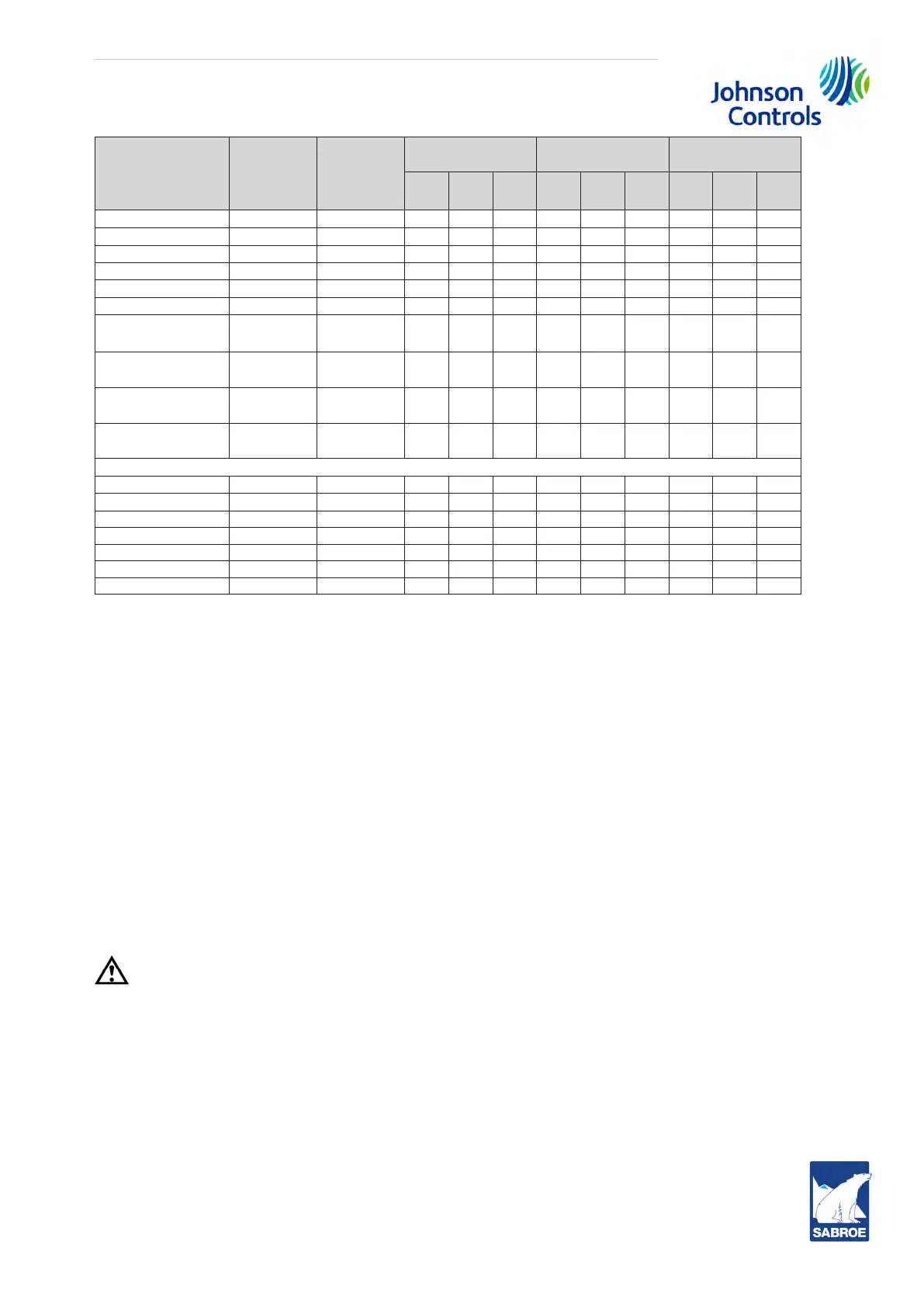
Parameter Unit Method
Sabroe oil
PAO 68
Sabroe oil
AP 68
Sabroe oil
A 100
Target
spec.
Max. Min.
Target
spec.
Max. Min.
Target
spec.
Max. Min.
Viscosity @40°C cSt ASTM D 445 66 76 53 64 74 51 100 115 80
TAN*1) mg KOH/g ASTM D 664 0.03 0.2
-
0.01 0.02
-
0.05 0.02
-
SAN*2) mg KOH/g ASTM D 665
-
0
- -
0
- -
0
-
Water
ppm
Karl Fisher
-
100
- -
100
- -
100
-
Apperarance
- -
report report report
Colour
-
ASTM D 1500
report report report
Pentane Insolubles
(Sum)
W% MM 490
-
0.05
-
0.05
- -
0.05
-
Oxidation abs/cm IR,1700-1720/
cm
-
5
- -
5
- -
5
-
Nitration abs/cm IR,1627-1637/
cm
-
5
- -
5
- -
5
-
Nitro Compounds abs/cm IR,1547-1557/
cm
-
0.5
- -
0.5
- -
0.5
-
Maximum values for metal content in the oil)
Lead
ppm
ICP
-
10
- -
10
- -
10
-
Copper
ppm
ICP
-
10
- -
10
- -
10
-
Silicium
ppm
ICP
-
25
- -
25
- -
25
-
Iron
ppm
ICP
-
100
- -
100
- -
100
-
Chromium
ppm
ICP
-
5
- -
5
- -
5
-
Aluminium
ppm
ICP
-
10
- -
10
- -
10
-
Tin
ppm
ICP
-
10
- -
10
- -
10
-
1) TAN (Total Acid Number) is only non-ammonia applications
2) SAN (Strong Acid Number) is only reported for non-ammonia applications
A report is compiled for every sample received. This report will describe:
• whether the oil can still be used without taking any further action.
• whether the oil can be used after it has been filtered through a very fine filter. If this is
necessary, the oil must be pumped directly from the compressor unit through a 3 mi-
cron filter and back to the unit. The system must be completely closed to prevent the oil
from being affected by moisture in the air.
• whether the oil can no longer be used.
The report will always be sent to the address stated on the sample label included in the form
set. A copy will be sent to Johnson Controls Denmark so that we are in a position to advise
you, if required.
11.12 Charging compressor with lubricating oil
Caution!
Only charge oil when the unit pressure is below 6 bar!
Oil charging is carried out by means of a portable oil charging pump, see Fig. 86. Proceed as
follows:
1. Connect the high-pressure hose, pos. 7, to the service valve, pos. 106, on the unit via
the non-return valve, pos. 12. Use the correct reduction nipple. See Fig. 87.
2. Place the free end of the suction hose from the pump, pos. 1, together with the by-pass
hose, pos. 2, in the barrel.
3. Open the ball valve, pos. 9, and service valve, pos. 106, and start the pump, pos. 5.
 Loading...