III - 8
Service Procedures
3
SM830063
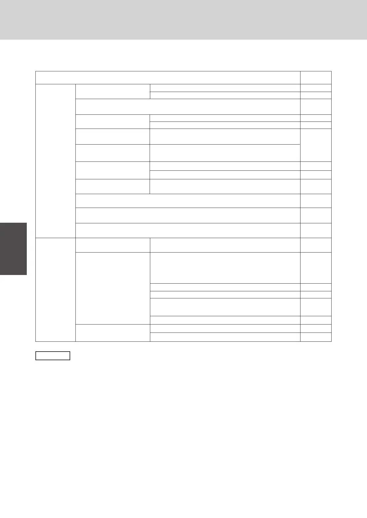
1-3. Explanation of Alarm Messages
1. Troubleshooting
Error in receiving serial communications signal.
Error in transmitting serial communications signal.
Error in receiving serial communications signal.
Error in transmitting serial communications signal.
Error in receiving serial communications signal.
• Indoor unit is damaged.
• Power is not supplied.
Indoor unit address setting is duplicated.
Remote controller address (RCU.ADR) switch is duplicated.
Do not press Auto. address button S001: (A. ADD) of another
R.C. line during Auto. address operation.
• Indoor unit is detecting error signal from the remote controller.
(No serial communications signal)
Remote controller is detecting
error signal from indoor unit.
Indoor unit is detecting error
signal from outdoor unit.
Outdoor unit is detecting error
signal from indoor unit.
Indoor unit is not working
correctly.
Improper setting of indoor unit or
remote controller.
• Serial
commu-
nication
errors
• Mis-setting
Possible Cause of Malfunction
Alarm
message
E1
E2
E3
E4
E5
E6
E8
E9
E12
E15
E16
E18
Error in Auto. address setting.
(No. or capacity of judged indoor unit is small.)
Error in Auto. address setting.
(No. or capacity of judged indoor unit is large.)
Indoor unit is detecting error signal from another indoor unit.
Activation of
protective
device
• Thermal protector in indoor fan motor is activated.
• Thermal protector in outdoor fan motor is activated.
• PC or AC Compressor thermal protector is activated.
• Power supply voltage is unusual. (The voltage is more than
270 V or less than 160 V between L and N phase.)
Incorrect discharge gas temp. of PC comp.
High-pressure switch is activated.
Incorrect power supply voltage . Negative phase, defective
phase or voltage drop.
Incorrect discharge gas temp. of AC comp.
Improper wiring connections of ceiling panel.
Float switch is activated.
Protective device in indoor unit
is activated.
Protective device in outdoor
unit is activated.
Protective device in indoor unit
is activated.
P1
P2
P3
P4
P5
P17
P9
P10
NOTE
● RCU : Remote Control Unit (remote controller)
● R.C. : Refrigerant Circuit
● PC : Power Control
● AC : Standard
● comp. : Compressor
● temp. : Temperature
● PCB : Printed Circuit Board
 Loading...
