III - 47
3
SM830063
Service Procedures
4-1. PCB Setting & Test Run
¶ Setting of outdoor PCB
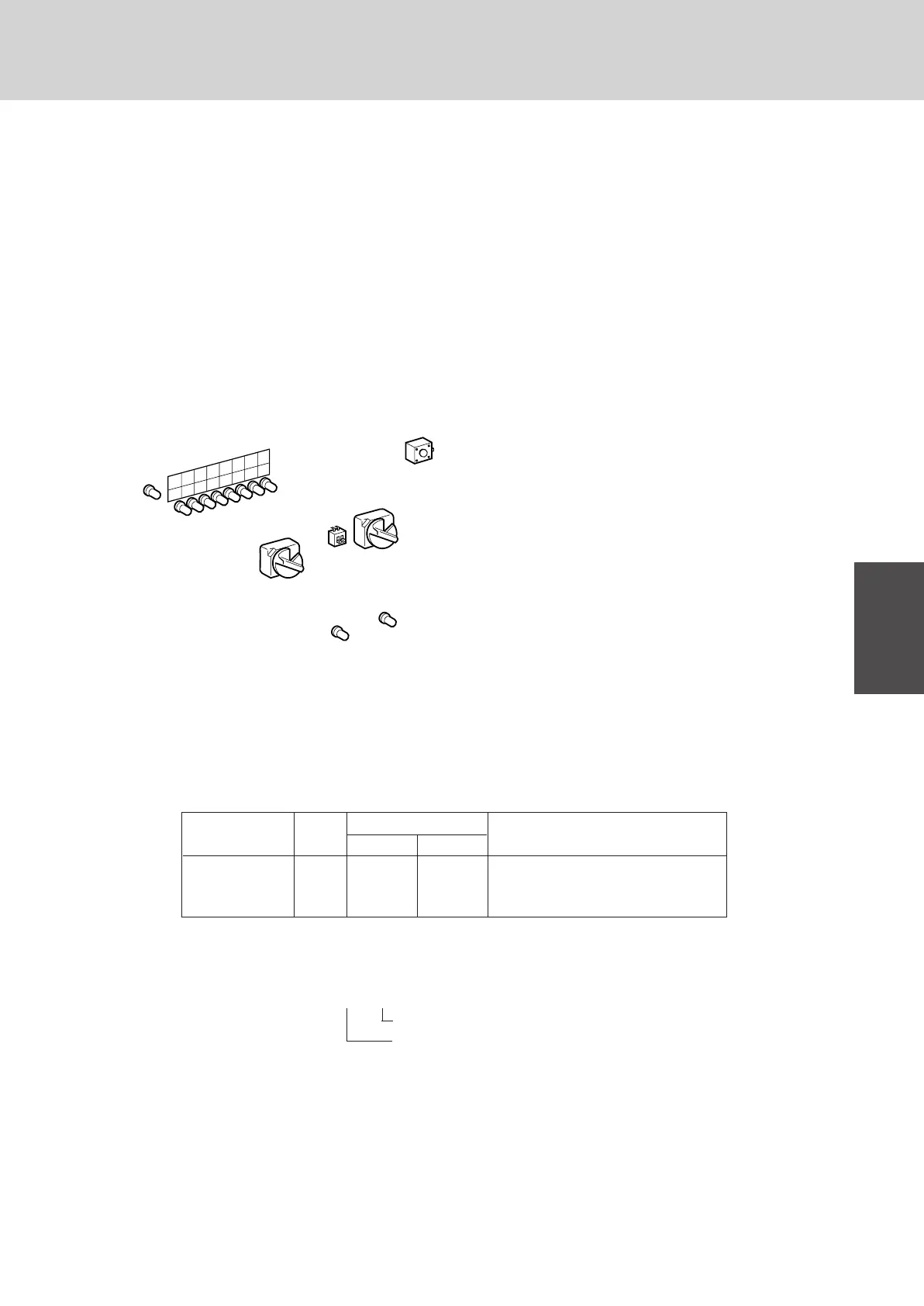
(A) Set the number of indoor units which are connected to the outdoor unit in S004.
a For example in the case of 13, set “D” in S004.
b If the number of indoor units and the number
of set switches are identical, the LED: 1 to 8
(9~16) light up matching the number of indoor
units.
c If the outdoor alarm LED (yellow) and LED: 2,
3, 6 light up when operating the indoor unit, it
is a combination fault. Check the number of
connected indoor units.
*(Remote controller shows the alarm of
display).
1S004 (RED) : Setting SW for number of indoor
units (0~16 or 1~10).
2S002 (BLK) : Setting SW for R.C. address of
the outdoor unit (0~9).
3S003 : Setting SW for R.C. address of
the outdoor unit (10, 20).
4RED LED 1 ~ 8 : Message lamp
5RED LED (9 ~ 16) : Message lamp
(only for 70, 90 type)
6D001 (RED) : Power lamp
7D083 (Yellow) : Outdoor unit alarm lamp
8S001 : A. ADD (Auto. address) button
(B) When linking outdoor units in a network (S-net link system).
a Set the R.C. address number of the outdoor unit in S002 and S003.
R.C. address : Refrigerant circuit address 1~30.
b Remove the short plug (CN031, 2P Black, location: right bottom on the outdoor control PCB) from all outdoor
units except one.
For a system without link, set the R.C. address number to 1 and retain the short plug CN031.
¶ Setting the indoor PCB
No setting necessary.
Each indoor unit address (UNIT No: R.C. - No.) is decided after auto. address operation.
Manual setting for indoor unit address can be performed also by remote controller.
¶ Check items before the test run
1 Turn on all power supply switches more than 5 hours before in order to charge the crank-case heater.
2 Fully open the outdoor service valve after making the leak inspection of field connected tubing, vacuuming, and
gas charging.
4. Test Run
R.C. address S002
S003
CN031
20 10
1 1 off off short (In case of No-link system)
12 2 off on open (In case of link system)
23 3 on off open (In case of link system)
Example,
S004
D001
D083
8
7
6
5
4
3
2
1
16
15
14
13
12
11
10
9
S003
10
20
on
off
S002
S001
A.ADD
0186_C_
3
4
5
6
7
2
8
1
Refrigerant Circuit No. (R.C. address)
Indoor unit No.
 Loading...
