III - 49
3
SM830063
Service Procedures
4. Test Run
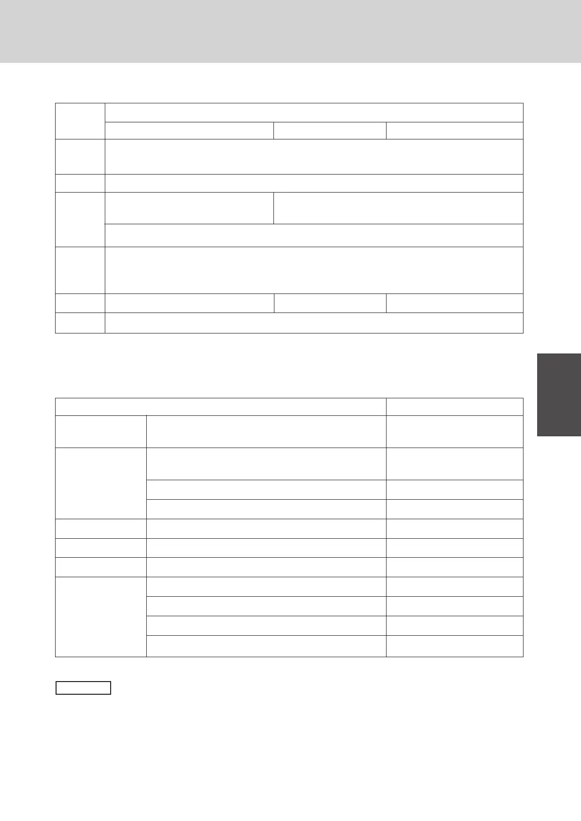
Fault detected Remote controller display
Indoor protection Fan motor protection thermostat P1
Outdoor protection Fan motor protection thermostat P2
Compressor protection thermostat
Incorrect discharge temp of PC (AC) comp. P3 (P17)
High-pressure switch P4
Indoor protection Float switch P10
Indoor sensor Open/or damaged F1-F3, F10, F11
Outdoor sensor Open/or damaged F4 ~ F8
Compressor PC comp. motor is overloaded. H1
protection
PC comp. motor is locked. H2
AC comp. motor is overloaded. H11
AC comp. motor is locked. H12
4-2. Main Alarm Messages which Indicate Mis-Wiring & Mis-Setting
Cause
• Individual Remote Control
• Remote controller not properly connected.
• Power supply not ON.
• Remote controller not properly connected.
• Wiring connection fault of
indoor/outdoor units
• Power supply of outdoor unit not ON.
• Combination of indoor/outdoor units is wrong.
* Incorrect setting of No. of indoor unit on outdoor control PCB. (S004 setting)
* Power supply of some indoor units not ON.
4-3. Main Alarm Messages Indicating Unit Malfunction
—
—
P9
(*)
E9
E6
E1
E4
* Ref: Alarm “P9” is not generated if the remote controller is set at test run.
• Improper wiring connections of ceiling panel
● comp.: Compressor
● temp.: Temperature
● PC: Power Control
● AC: Standard
NOTE
Remote
controller
display
Nothing
displayed
• 2 main remote controllers set.
Group Control Multiple Remote Control
• Wiring connection fault of some indoor/outdoor units
inside the group
 Loading...
