PN-L803C/80TC3 IMPORTANT INFORMATION FOR SERVICING THE DISPLAY 3-3
1-3. LCD MODULE UNIT REPLACEMENT PROCEDURES
1) Replace the LCD Module Unit.
2) Set “0” to USAGE TIME and perform initialization.
3) Reset the WHITE BALANCE set values.
4) Reset the GAMMA set value.
5) Adjust the flicker.
→Refer to “21. FLICKER ADJUSTMENT TOOL”
6) Make the test pattern displayed, and check to confirm that all the patterns are displayed.
→Refer to “18. TEST PATTERN TOOL”
7) Reset system log information.
→Refer to “6-5. SYSTEM LOG AND TEMPERATURE LOG INITIALIZATION”
→Refer to “12-8. OTHER FUNCTIONS”.
1-4. T-CON PWB REPLACEMENT PROCEDURES
1) Replace the T-CON PWB.
2) Adjust the flicker.
→Refer to “19. FLICKER ADJUSTMENT TOOL”
3) Make the test pattern displayed, and check to confirm that all the patterns are displayed.
→Refer to “17. TEST PATTERN TOOL”
1-5.TOUCH PANEL UNIT REPLACEMENT PROCEDURE
1) Replace the touch panel unit. .
2) Perform the Touch Panel Calibration tool from the Service Tool and adjust the touching position.
-> Refer to “20 HOW TO USE TOUCH PANEL CALIBRATION TOOL ”.
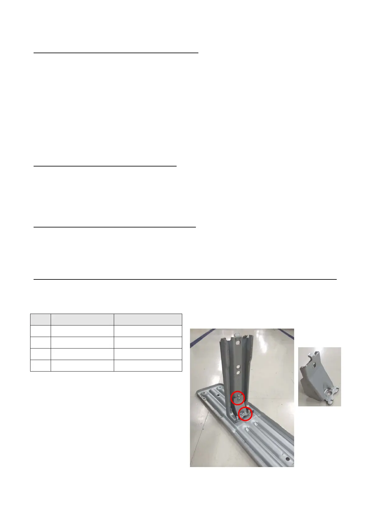
2. TEMPORARY STAND
When the machine is fixed to the temporary stands, use the temporary stand which is set up with PN-L802B monitor.
* When disassembling or assembling the monitor, be sure to lay the monitor and perform disassembling or assembling.
No. Parts code Parts name
①
CANGKD276WJ04 Temporary stand B As
②
LANGKD403WJFW Temporary stand A
③
XBPS760P20JS0 Screw (M6×20)(White)
④
XBPS750P14JS0 Screw (M5×14)(White)
*Unscrew the screws (x2) from Temporary Stand B and remove
the Reinforce plate.
[Reinforce plate]
 Loading...