Accessories
A.5 LTOP overvoltage protection modules
TIM DNP3
328 System Manual, 12/2015, C79000-G8976-C253-04
LTOP line transformer with overvoltage protection
Introduction
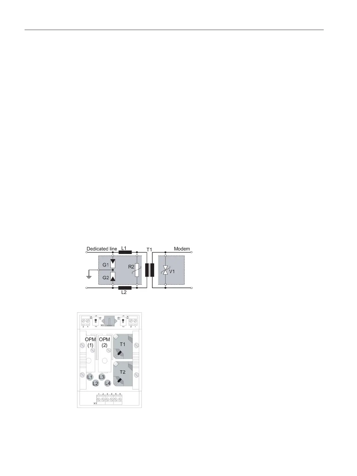
Copper dedicated lines are highly susceptible to electromagnetic interference. The coupling
of extraneous voltages can be inductive or capacitive, for example due to the effects of
lightning. Direct conductive coupling is also possible due to bad insulation.
The LTOP (
ine
ransformer with
vervoltage
rotection) limits extraneous voltages and
overvoltages to a non-critical level. The floating transformer also provides electrical isolation
preventing coupling of voltages into other cable sections.
The protection concept involves a combination of components whose functions supplement
each other:
● Overvoltage suppressors filled with inert gas providing protection against high voltage
(G1, G2)
● Inductors that limit the rise in current (L1, L2)
● Metal oxide varistors as fine protection (voltage dependent resistance; R1)
● Transformer for electrical isolation (T1)
● Suppressor diode to limit the secondary voltage of the transformer (V1)
Image A-12 Circuit diagram of an LTOP unit
Image A-13 Location of the circuit elements of an LTOP 2 (view from above)

 Loading...


