LEDs and connectors
3.2 TIM 4R-IE DNP3
TIM DNP3
58 System Manual, 12/2015, C79000-G8976-C253-04
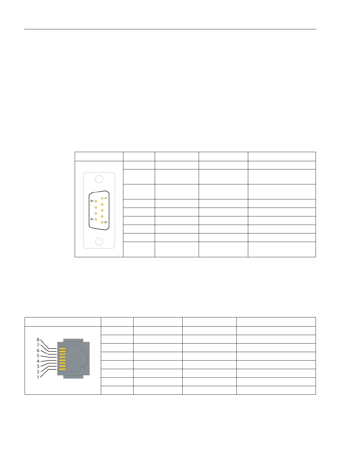
Pinout of the ports
RS-232/RS-485 interfaces
The plugs for the two serial ports are designed as a 9-pin D-sub miniature connectors
(male). The pinout of the two connectors is identical and is shown in the following table. As
an RS-232 port, the pinout corresponds to that of a standardized PC connector.
This is a combined RS-232/RS-485 port. As default, the ports are set to RS-232. The
switchover to RS-485 is set in the STEP 7 configuration and is therefore part of the
configuration data of the TIM 4R-IE DNP3.
Table 3- 7 Pinout of the connector of the combined RS-232/RS-485 port
2 RXD Input Switching over to RS-485
in the configuration
3 TXD Output Switching over to RS-485
9 -
The two Ethernet ports are designed as 8-pin RJ-45 Western jacks. The pinout is shown in
the following table.
Table 3- 8 Pinout of the RJ-45 Western jack for the Ethernet port

 Loading...


