Service cases - hardware
4.8 SINAMICS S120 Combi
Hardware and Software
128 Service Manual, 03/2011, 6FC5397-5DP40-0BA0
4.8.7 This is how you connect the DC link busbars and 24 V busbars
Connecting additional components
The following steps are necessary to connect a component to the DC link and the 24 V
busbars of the S120 Combi.
CAUTION
Before commissioning the drive line-up, it must be ensured that following items are
complied with:
The outer DC link side cover is inserted at the connected component.
The protective cover of the connected component is closed.
The front cover of the S120 Combi has been reinstalled.
CAUTION
After removing the additional components, before recommissioning the system, the touch
protection of the DC link busbars on the S120 Combi power module must be reinstalled.
The touch protection can be ordered as a spare part.
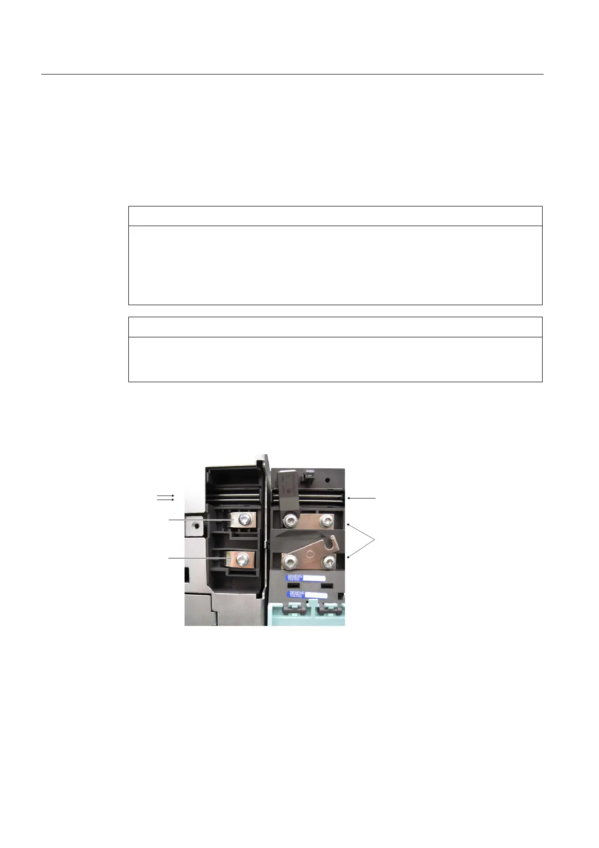
Procedure:
1. Use a suitable tool to open the protective cover of the component to be connected
2. Remove the DC link side cover at the connection location.
9EXVEDUV
'&OLQNEXVEDUV
0RWRU0RGXOH
%RRNVL]H&RPSDFW
6&RPEL
0
'&3
'&1
3. Use the following tool to install the DC link busbar:
Screwdriver: Torx T20 or slotted 1.2 x 6
Tightening torque: 1.8 Nm

 Loading...


