Service cases - hardware
4.15 Sensor Modules External
Hardware and Software
194 Service Manual, 03/2011, 6FC5397-5DP40-0BA0
4.15.7 SME125 connections
Overview
The activities that must be taken into account when replacing an Sensor Module External
SME125 are subsequently described.
If an SME125 has a hardware defect, then it must be replaced by an identical module.
Preconditions:
● The module is defective and must be replaced.
● The control cabinet is in a no-voltage condition, all of the connectors and cables are
labeled.
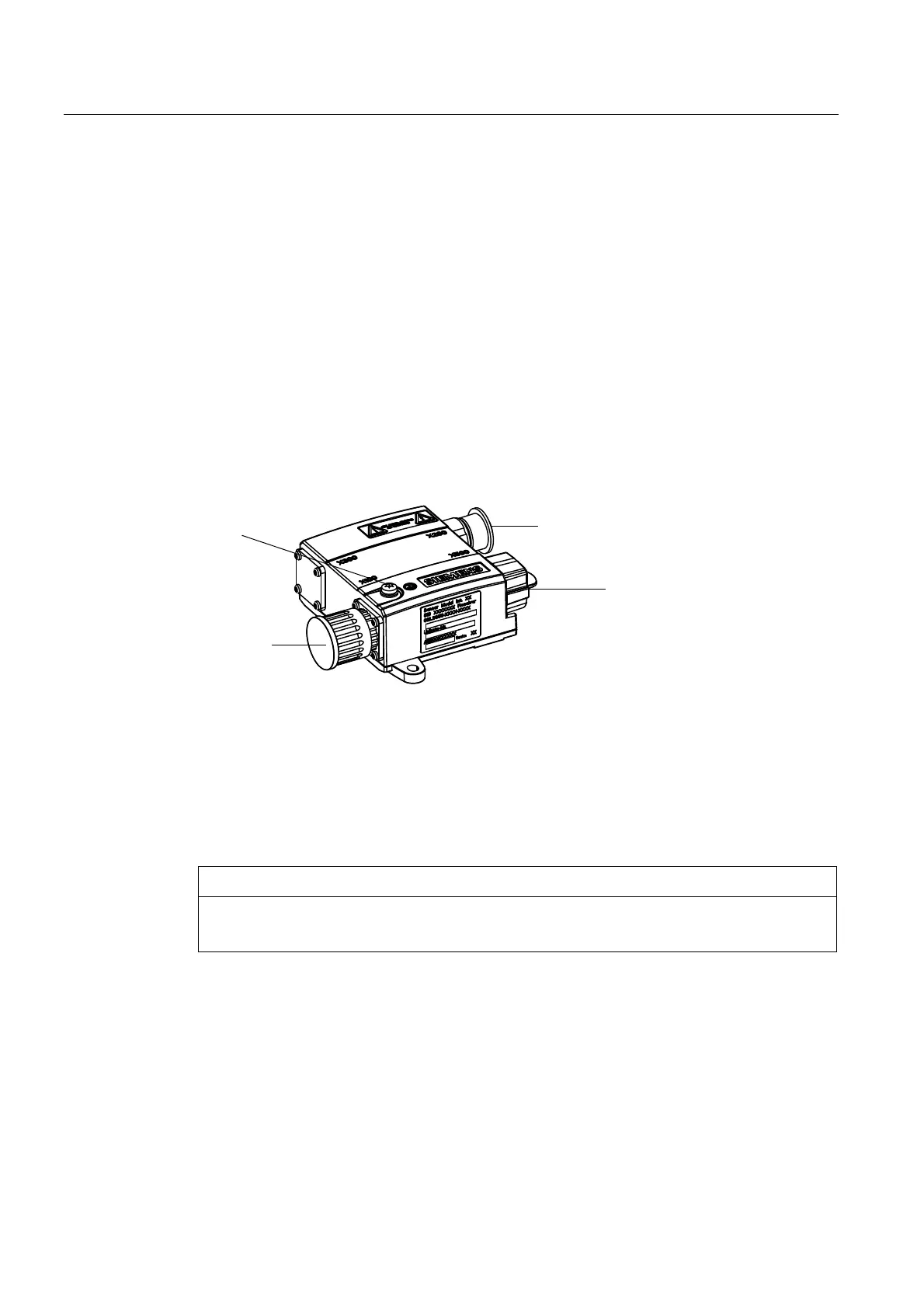
Connections
;HQFRGHUV\VWHPLQWHUIDFH
7LJKWHQLQJWRUTXH1P
;WHPSHUDWXUHVHQVRULQSXW
7LJKWHQLQJWRUTXH1P
'5,9(&/L4
LQWHUIDFH;
3URWHFWLYHFRQGXFWRUFRQQHFWLRQ
0VFUHZ
7LJKWHQLQJWRUTXH1P
0LQLPXPFURVVVHFWLRQPP
Figure 4-46 SME125 connections
4.15.8 This is how you remove an SME125 and install it again
Removing
NOTICE
Electrostatic discharge (ESD)
Before you touch the module, discharge yourself at the ground terminal.
Procedure:
1. Release the encoder connecting cable X100 of the SME125
2. Withdraw the DRIVE-CLiQ cable from X500 of the SME125.
3. Release the temperature sensor input X200 of the SME125.
4. Release the protective conductor connection of the SME125.
5. Remove the defective SME125 module.

 Loading...


