[tdio102x-220513-01.tif, 1, en_US]
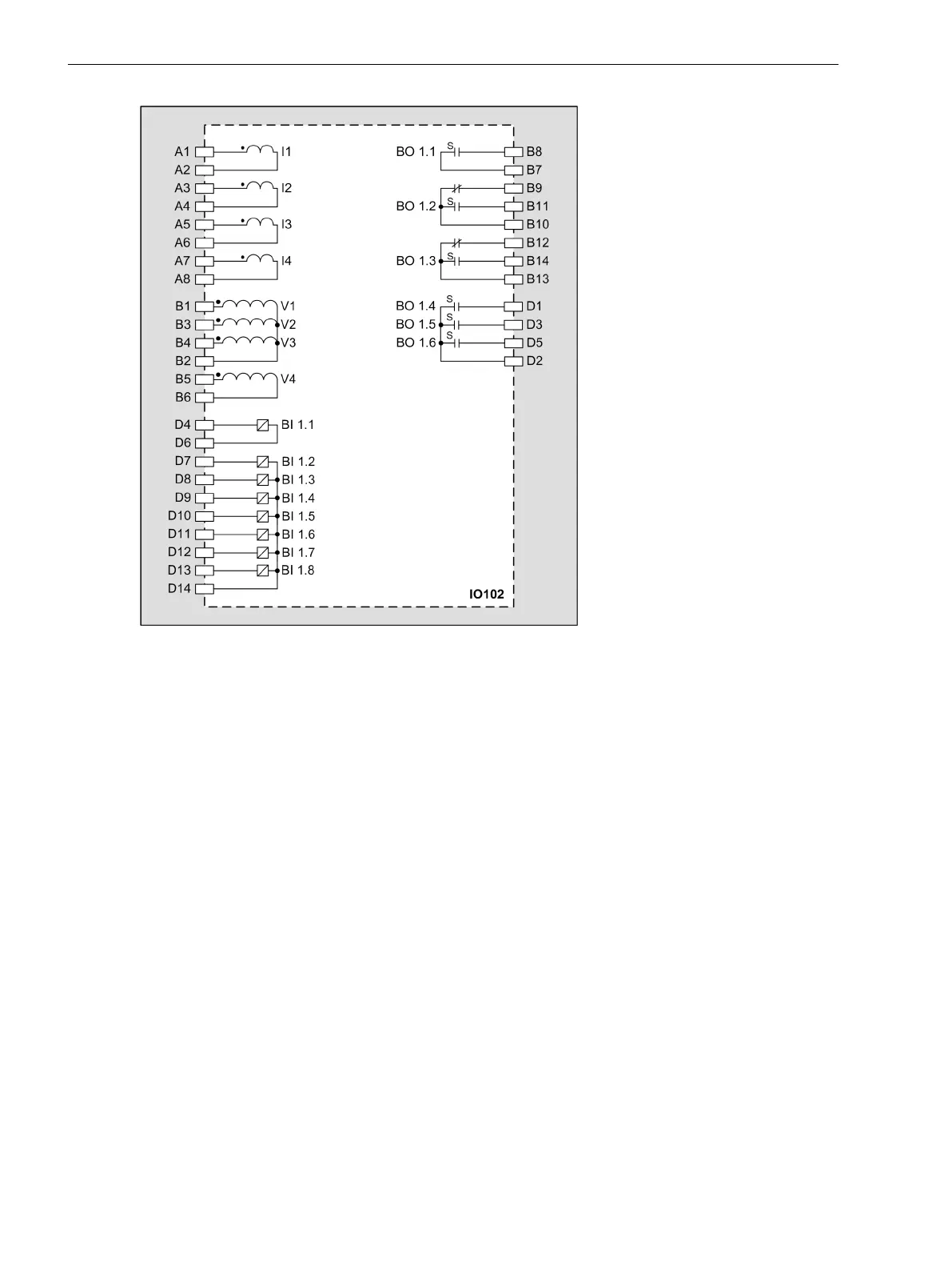
Figure 3-70
IO102 – Connection Diagram
Input and Output Module IO103
Description
The terminals for the following are located on the input and output module IO103:
•
8 current transformers (optionally as protection-class current transformers or instrument transformers)
•
4 binary inputs (2 binary inputs each with common connection)
•
4 binary outputs with 4 standard make contacts (type S)
The connections are distributed over:
•
2 x 8-pole current terminal
•
1 x 14-pole voltage terminal
3.4.4
3.4.4.1
Electronic Modules
3.4 Input and Output Modules of the Non-Modular Devices (7xx82)
114 SIPROTEC 5, Hardware Description, Manual
C53000-G5040-C002-C, Edition 10.2017

 Loading...


