Terminals
Overview of Terminals
[le_ps201, 1, --_--]
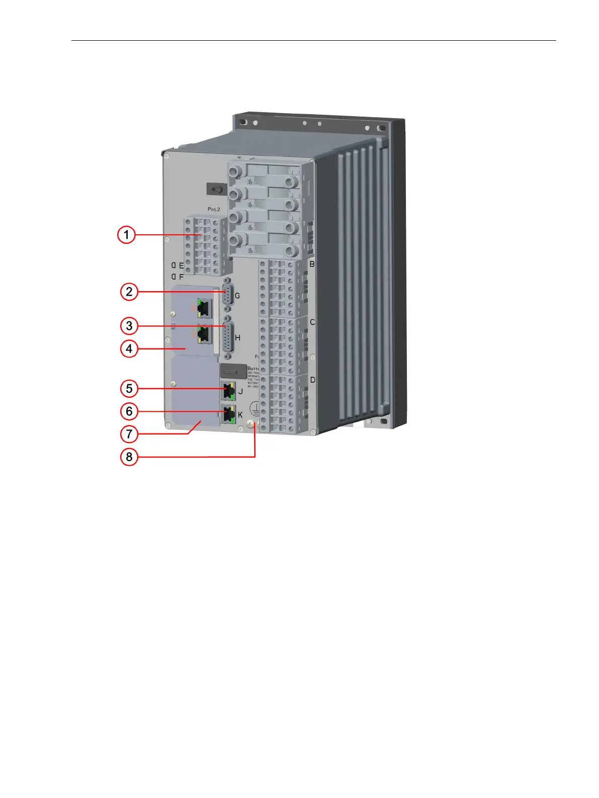
Figure 3-1
PS201 – Terminals
(1) Voltage terminal 2B
(2) Time synchronization G
(3) Detached on-site operation panel H
(4) Plug-in module position E
(5) Integrated Ethernet interface J
(6) COM link K, connection to the CB202 PCB assembly (plug-in module assembly), position K
(7) Plug-in module position F
(8) Protective grounding terminal
3.1.2.2
Electronic Modules
3.1 Power-Supply Modules of the Modular Devices
SIPROTEC 5, Hardware Description, Manual 45
C53000-G5040-C002-C, Edition 10.2017

 Loading...


