Input and Output Module IO207
Description
The terminals for the following are located on the input and output module IO207:
•
16 binary inputs
•
8 binary outputs with 8 standard make contacts (type S)
The connections are distributed over four 14-pole voltage terminals.
Terminals
Overview of Terminals
[dwio207p-030211-01.tif, 2, --_--]
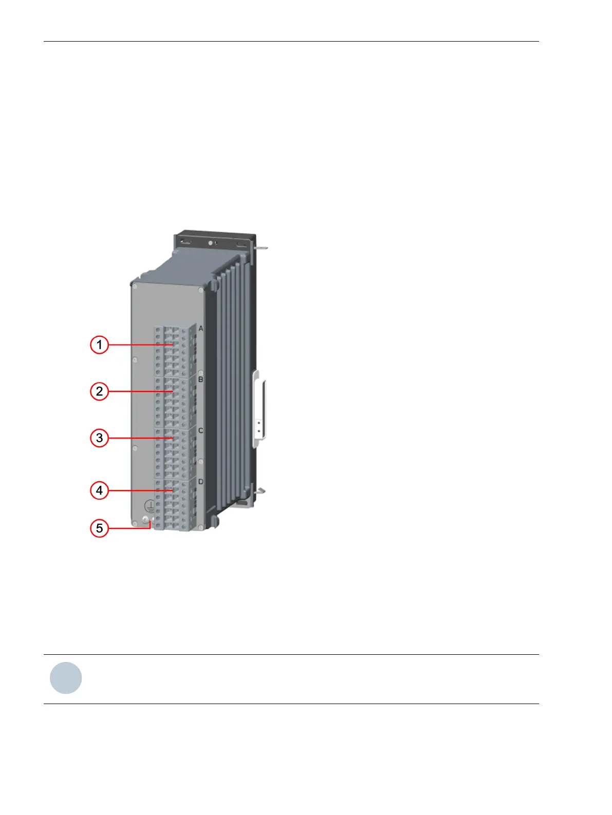
Figure 3-31
IO207 – Terminals
(1) Voltage terminal xA
(2) Voltage terminal xB
(3) Voltage terminal xC
(4) Voltage terminal xD
(5) Protective grounding terminal
NOTE
x corresponds to the slot in the 19-inch rack.
3.2.8
3.2.8.1
3.2.8.2
Electronic Modules
3.2 Input and Output Modules of the Modular Devices
72 SIPROTEC 5, Hardware Description, Manual
C53000-G5040-C002-C, Edition 10.2017

 Loading...


