[tdio203x-110313-01.tif, 1, en_US]
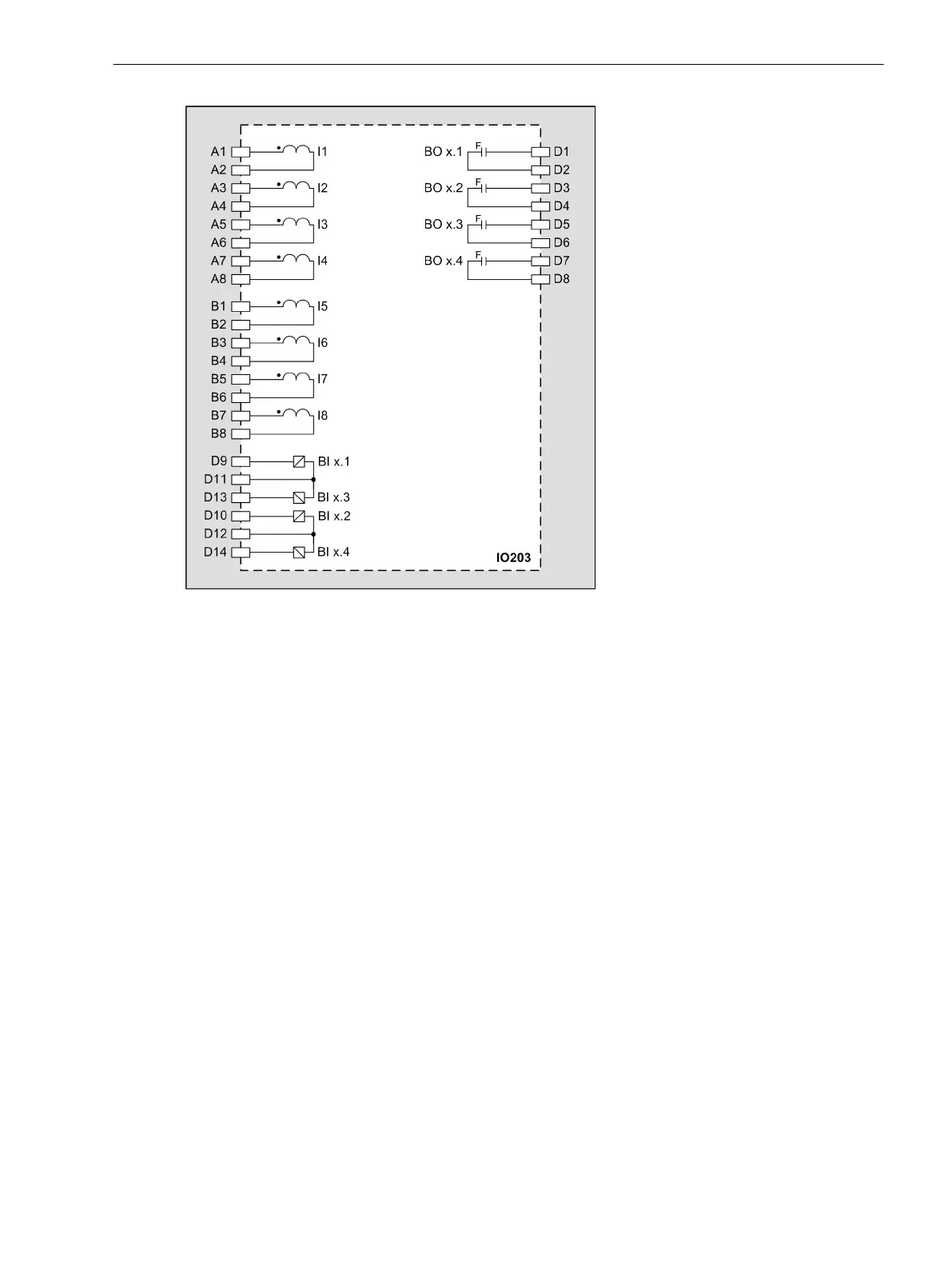
Figure 3-21
IO203 – Connection Diagram
Input and Output Module IO204
Description
The terminals for the following are located on the input and output module IO204:
•
10 binary inputs
•
4 binary outputs with 4 standard make contacts (type S)
•
4 power relays for controlling 2 motors (forward/backward) with a common auxiliary voltage supply V
aux
+, V
aux
-
The power relays operate in interlocked mode, that is, only one relay of each switching pair picks up at a
time thereby avoiding a power-supply short circuit. Note the polarity specified in the terminal and
connection diagram.
The connections are distributed over three 14-pole voltage terminals.
3.2.5
3.2.5.1
Electronic Modules
3.2 Input and Output Modules of the Modular Devices
SIPROTEC 5, Hardware Description, Manual 63
C53000-G5040-C002-C, Edition 10.2017

 Loading...


