EasyManuals Logo
Home>Siemens>Controller>SIPROTEC 5

Siemens SIPROTEC 5 Hardware Description

Siemens SIPROTEC 5
254 pages
To Next Page IconTo Next Page
To Previous Page IconTo Previous Page
Page #77 background imageLoading...
Page #77 background image
[tdio208x-300812-01.tif, 1, en_US]
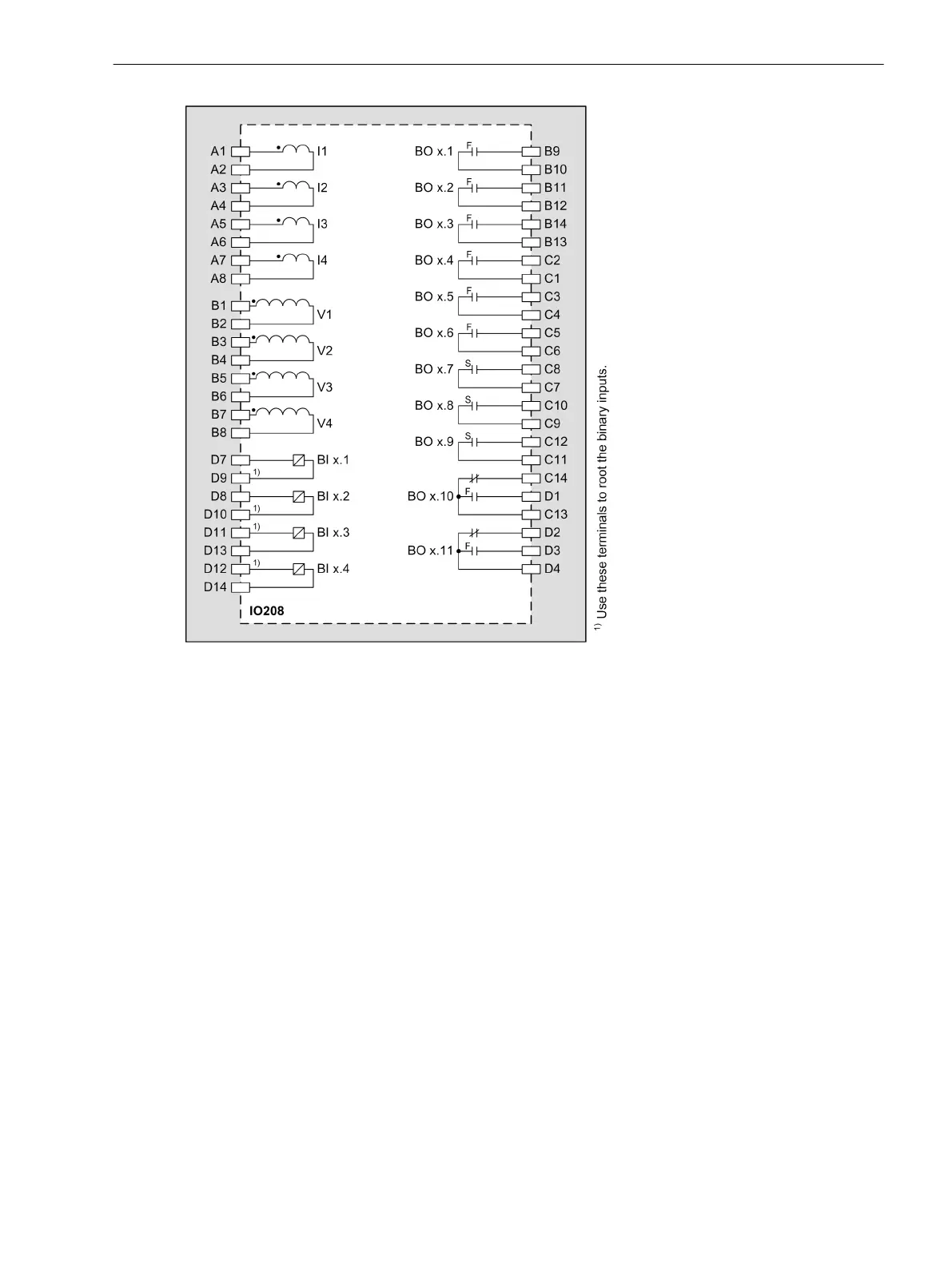
Figure 3-36
IO208 – Connection Diagram
Input and Output Module IO209
Description
The terminals for the following are located on the input and output module IO209:
8 binary inputs
4 binary outputs with semiconductor-accelerated make contacts (type HS)
The connections are distributed over three 14-pole voltage terminals.
3.2.10
3.2.10.1
Electronic Modules
3.2 Input and Output Modules of the Modular Devices
SIPROTEC 5, Hardware Description, Manual 77
C53000-G5040-C002-C, Edition 10.2017

Table of Contents

Other manuals for Siemens SIPROTEC 5

Questions and Answers:

Question and Answer IconNeed help?

Do you have a question about the Siemens SIPROTEC 5 and is the answer not in the manual?

Siemens SIPROTEC 5 Specifications

General IconGeneral
BrandSiemens
ModelSIPROTEC 5
CategoryController
LanguageEnglish

Related product manuals