Plug-In Modules
Fasteners
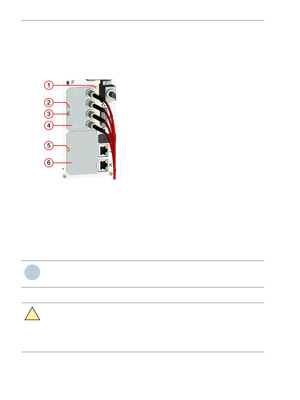
The fasteners of the plug-in modules are shown in the following figure regarding the example of an installed
module and an empty, covered slot.
[le_fxing_elements, 1, --_--]
Figure 5-11 Fasteners
(1) EMC spring contact
(2) Fastening screw
(3) Cut-out for prying out the modules
(4) Plug-in module
(5) Fastening screw
(6) Cover plate
Installation
NOTE
Reordered modules are not contained in the original device configuration. Use DIGSI to perform the corre-
sponding extension in the Hardware and Protocols Editor.
Preparing Installation
DANGER
Danger due to live voltage when installing the plug-in modules.
Noncompliance with the safety notes will result in death or severe injuries.
²
Install plug-in modules on the electrically deactivated device only.
5.3
5.3.1
5.3.2
Working on the Device
5.3 Plug-In Modules
168 SIPROTEC 5, Hardware Description, Manual
C53000-G5040-C002-C, Edition 10.2017

 Loading...


