Measuring-Transducer Modules
Overview
You can install the measuring-transducer modules in base modules or 1/3 modules (plug-in module positions E
and F) and in expansion modules with a CB202 module (plug-in module position M, N, or P).
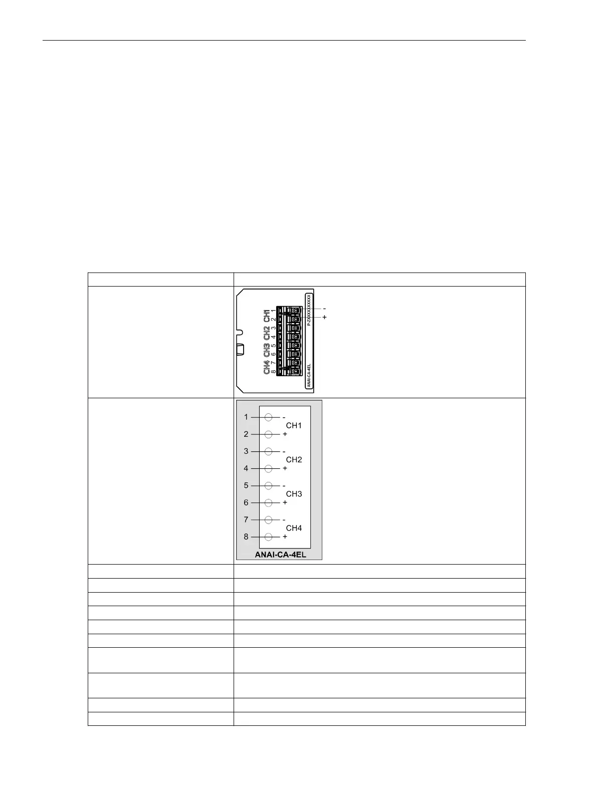
ANAI-CA-4EL
The ports CH1 to CH4 of the measuring-transducer modules are Safety Extra Low Voltage circuits (SELV
circuits). For the connection to the measuring-transducer modules, the following conditions apply:
•
SELV circuits may be connected only to SELV circuits.
•
Ensure that the cables of SELV circuits are routed separately from the supply circuits.
•
Use shielded cables.
Product Code P1Zxxxxxxxxxxx
Figure
Terminal diagram
Connector type 8-pin terminal spring
Differential current input channels 4
Measuring range DC -24 mA to +24 mA
Error limit 0.5 % of measuring range
Input impedance 140 Ω
Conversion principle Delta-sigma (16 bit)
Permissible potential difference
between channels
DC 20 V
Galvanic separation with respect to
ground/housing
AC 500 V, DC 700 V
Permissible overload DC 100 mA continuously
Measurement repetition 200 ms
4.3
4.3.1
4.3.2
Plug-In Modules
4.3 Measuring-Transducer Modules
150 SIPROTEC 5, Hardware Description, Manual
C53000-G5040-C002-C, Edition 10.2017

 Loading...


