[td_io111, 1, en_US]
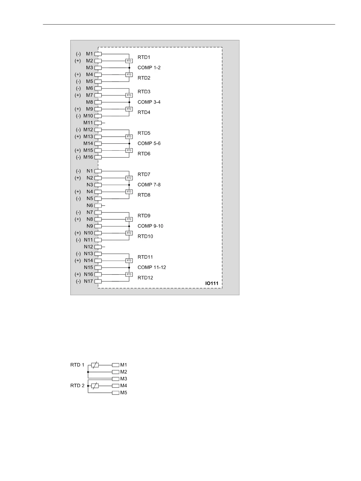
Figure 3-79
IO111 – Connection Diagram
Connections of Temperature Sensors and Cables
Connections of Temperature Sensors Directly to the Device
It is possible in principle to connect temperature sensors with 2-phase or 3-phase technology. To achieve the
specified accuracy, Siemens recommends only using 3-phase technology.
[dw_example_temp_sensor_3phase, 1, en_US]
Figure 3-80 Example: Connecting Temperature Sensors RTD 1 (3-Line Terminal) and RTD 2 (3-Line
Terminal) to Terminals M1 to M5
²
For a connection with 2-phase technology, you must connect a bridge, for example for RTD 2, between
M3 and M4.
3.4.6.3
Electronic Modules
3.4 Input and Output Modules of the Non-Modular Devices (7xx82)
SIPROTEC 5, Hardware Description, Manual 123
C53000-G5040-C002-C, Edition 10.2017

 Loading...


