[tdio209x-270812-01.tif, 1, en_US]
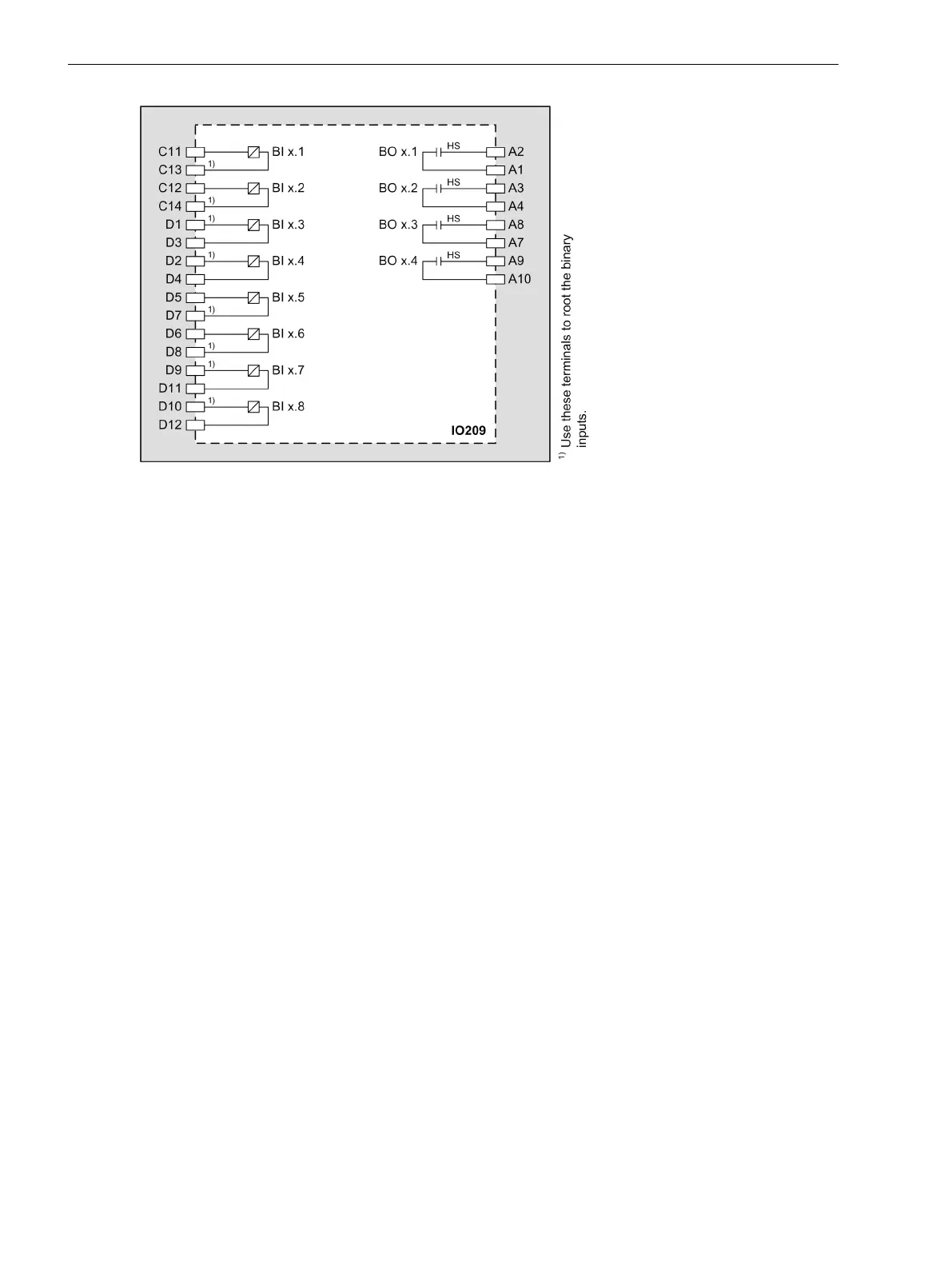
Figure 3-39 IO209 – Connection Diagram
Input and Output Module IO210
Description
The terminals for the following are located on the input and output module IO210:
•
4 current transformers (optionally protection-class current transformers or instrument transformers)
•
3 voltage transformers
•
4 high-speed measuring transducer inputs for current (20 mA) or voltage (10 V)
•
7 binary outputs, of which:
– 1 standard make contact (type S)
– 4 high-speed make contacts (type F)
– 2 standard change-over contacts (type S)
The connections are distributed over:
•
1 x 8-pole current terminal
•
3 x 14-pole voltage terminal
3.2.11
3.2.11.1
Electronic Modules
3.2 Input and Output Modules of the Modular Devices
80 SIPROTEC 5, Hardware Description, Manual
C53000-G5040-C002-C, Edition 10.2017

 Loading...


