Expanding Modular Devices
Flush-Mounting Devices
Basic Rules for Expansion
NOTE
Prepare the following tools for the device expansion:
•
Phillips screwdriver size PZ1 and PZ2
•
Screwdriver DIN 4 x 0.8
•
During assembly, use the prescribed torques (see chapter 6.13 Design Data).
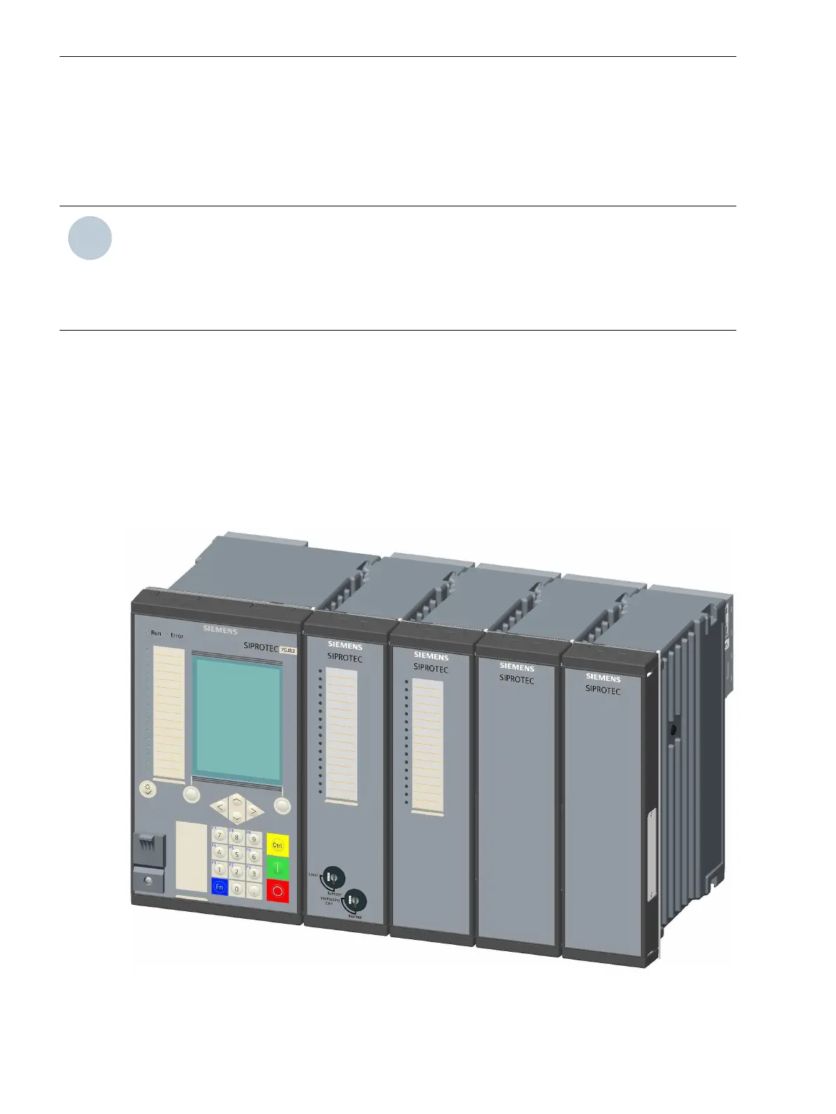
Comply with the following basic rules when expanding devices:
²
Always fit the base module on the left in the 1st device row.
²
Always fit the expansion modules from left to right.
²
Always fit the expansion module with the key switches as the 1st module next to the base module.
²
Always fit the expansion modules without LEDs last.
²
Always install a power-supply module PS203 on the left as the first unit in the 2nd device row.
²
Note that the PS203 must always have the same rated voltage as the base module.
²
Install only I/O modules without LEDs in the 2nd device row.
[dweinzei-030211-01.tif, 2, --_--]
Figure 5-1
Device Row of a Flush-Mounting Device
5.2
5.2.1
5.2.1.1
Working on the Device
5.2 Expanding Modular Devices
156 SIPROTEC 5, Hardware Description, Manual
C53000-G5040-C002-C, Edition 10.2017

 Loading...


