[td_io210, 2, en_US]
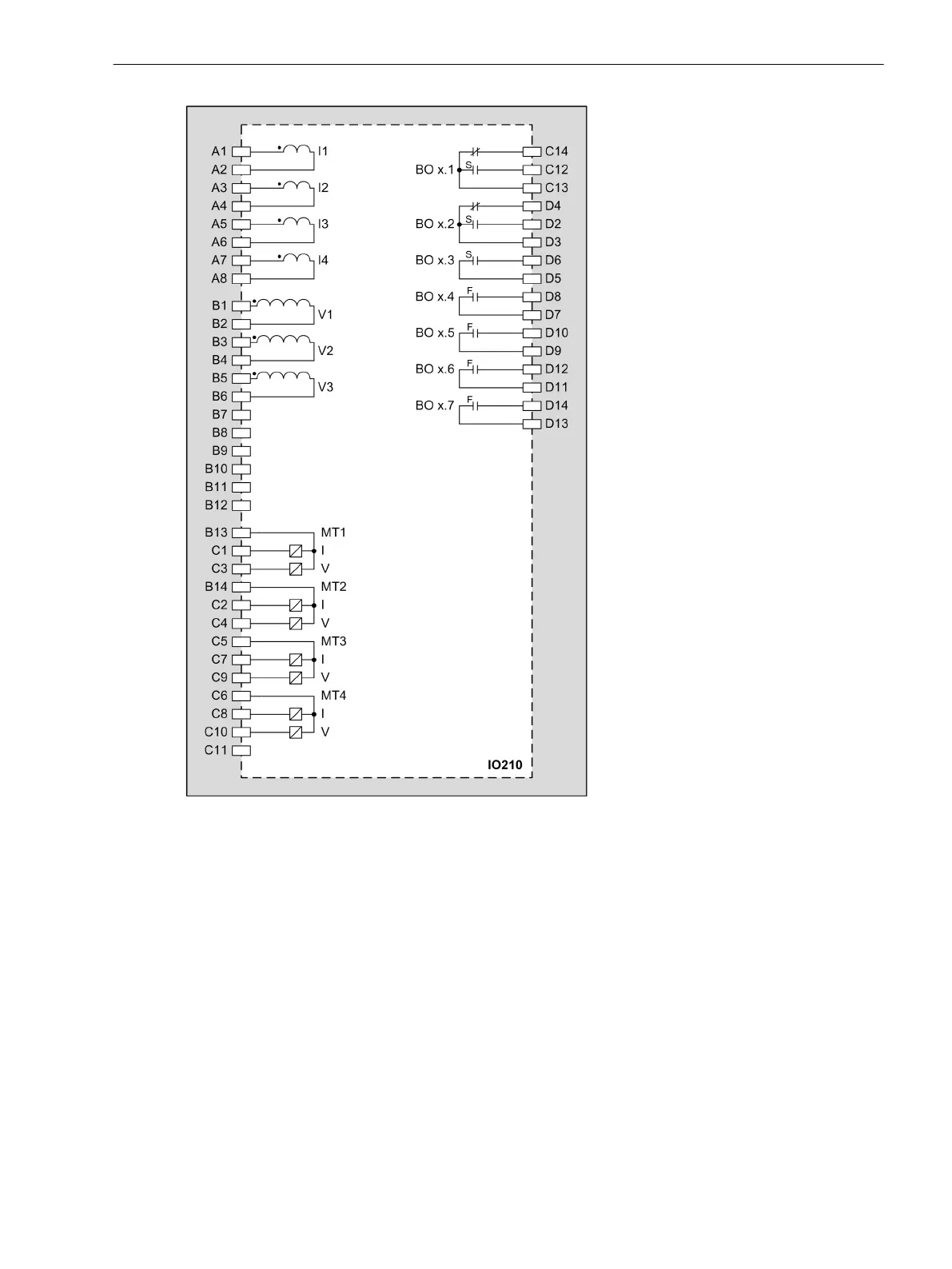
Figure 3-42
IO210 – Connection Diagram
Input and Output Module IO211
Description
The terminals for the following are located on the input and output module IO211:
•
8 voltage inputs
•
8 binary inputs
The connections are distributed over three 14-pole voltage terminals.
3.2.12
3.2.12.1
Electronic Modules
3.2 Input and Output Modules of the Modular Devices
SIPROTEC 5, Hardware Description, Manual 83
C53000-G5040-C002-C, Edition 10.2017

 Loading...


