[tdio201x-290812-01.tif, 1, en_US]
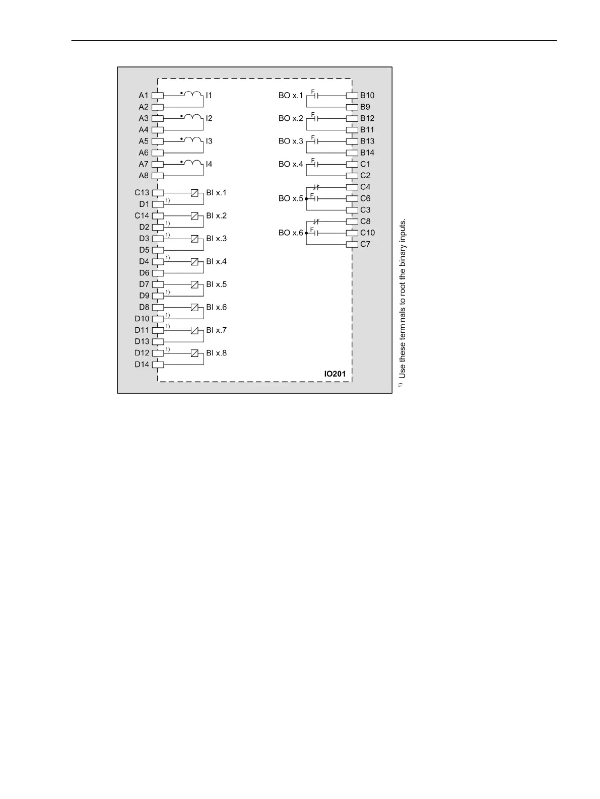
Figure 3-15
IO201 – Connection Diagram
Input and Output Module IO202
Description
This input and output module is used as the base measurement module in all protection devices and bay units.
One device can contain several IO202 input and output modules. The number of IO202 input and output
modules depends on the measured values required. Up to 40 measuring channels are possible for each
SIPROTEC device.
The terminals for the following are located on the input and output module IO202:
•
4 current transformers (optionally protection-class current transformers or instrument transformers)
•
4 voltage transformers
•
8 binary inputs
•
6 binary outputs, of which:
– 4 high-speed make contacts (type F)
– 2 high-speed change-over contacts (type F)
The connections are distributed over:
•
1 x 8-pole current terminal
•
3 x 14-pole voltage terminal
3.2.3
3.2.3.1
Electronic Modules
3.2 Input and Output Modules of the Modular Devices
SIPROTEC 5, Hardware Description, Manual 57
C53000-G5040-C002-C, Edition 10.2017

 Loading...


