Bridges can be used as an alternative for horizontally arranged clamping points. If bridges are used, only ring-
type lugs may be used.
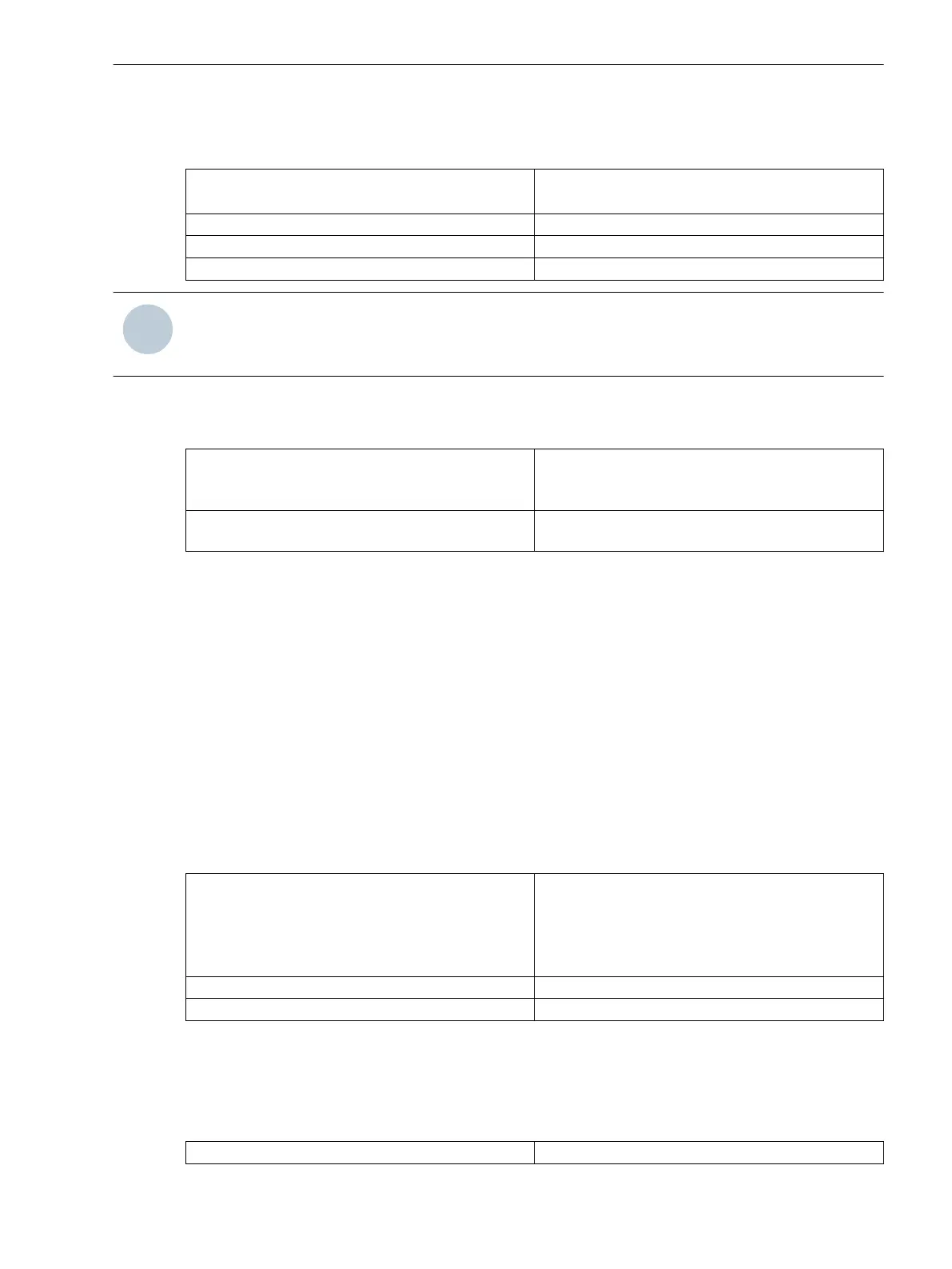
The following cable cross-sections can be used for the connection of single cables:
Cable cross-section AWG (American Wire Gauge) 14-10
(2.0 mm
2
to 4.0 mm
2
(0.0031 in
2
to 0.0062 in
2
))
Ferrule with plastic shroud L = 10 mm (0.39 in) or L = 12 mm (0.47 in)
Stripped length 15 mm (0.59 in)
For use without ferrule Use solid copper cables only.
NOTE
Always guide the solid conductor or stranded-wire conductor with bootlace from the left- or right-hand side
ferrule into the terminal. Making contact from the center is not permitted.
Mechanical Requirements
The fasteners and their associated components are designed for the following mechanical requirements:
Permissible tightening torque at clamping screw 2.7 Nm
For solid conductors, the max. permissible tightening
torque is 2 Nm.
Permissible tensile force for each connected
conductor
80 N following IEC 60947-1 (VDE 660, part 100)
Connections of Voltage Terminals
Connections of Voltage Terminals with Spring Clips
Fasteners
The fasteners for the voltage connection are part of the voltage terminal (housing side). They are made of a
stress-crack and corrosion-free alloy. The head shape of the clamping screw allows the use of a DIN 4.0 x 0.8
screwdriver or a PZ1 screwdriver. Siemens recommends a PZ1 screwdriver.
Connection Elements and Conductor Cross-Sections
The single cable connection type is available for the connection. You can connect solid conductors as well as
stranded-wire conductors with and without ferrules as single cables. Siemens recommends the use of twin
ferrules of series PN 966 144 made by Tyco Electronics for the connection of 2 single cables.
The following cable cross-sections can be used for the connection of single cables:
Cable cross-section
AWG (American Wire Gauge) 20-14 (0.5 mm
2
to
2.5 mm
2
(0.0008 in
2
to 0.0039 in
2
)) solid
or cable with UL listed ferrules
Use copper conductors only, at least certified for a
temperature of +105 °C.
Ferrule with plastic shroud L = 12 mm (0.47 in)
(Stripped length) for use without ferrule 12 mm (0.47 in), only copper lines may be used.
Single cables and bridges can be connected together for horizontally arranged clamping points. Note that
adjacent bridges are installed reciprocally.
Mechanical Requirements
The fasteners and their associated components are designed for the following mechanical requirements:
Permissible tightening torque at clamping screw
1.0 Nm
5.7.3
5.7.3.1
Working on the Device
5.7 Installing Current and Voltage Terminals
SIPROTEC 5, Hardware Description, Manual 187
C53000-G5040-C002-C, Edition 10.2017

 Loading...


