Terminal and Connection Diagram
For the binary inputs and outputs, the x corresponds to the slot in the 19-inch rack.
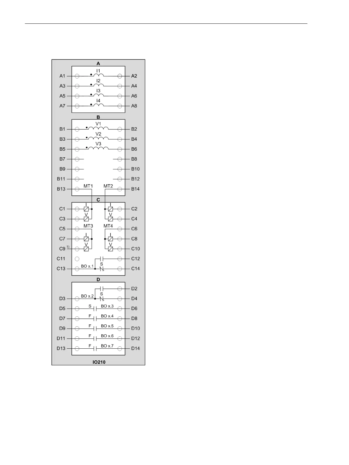
[cd_io210, 2, en_US]
Figure 3-41
IO210 – Terminal Diagram
(1) Voltage input MT3 with higher voltage immunity (maximum continuous voltage ± 60 V)
Electronic Modules
3.2 Input and Output Modules of the Modular Devices
82 SIPROTEC 5, Hardware Description, Manual
C53000-G5040-C002-C, Edition 10.2017

 Loading...


