Functions
2.23 Thermal Overload Protection
SIPROTEC, 7SD5, Manual
C53000-G1176-C169-5, Release date 02.2011
415
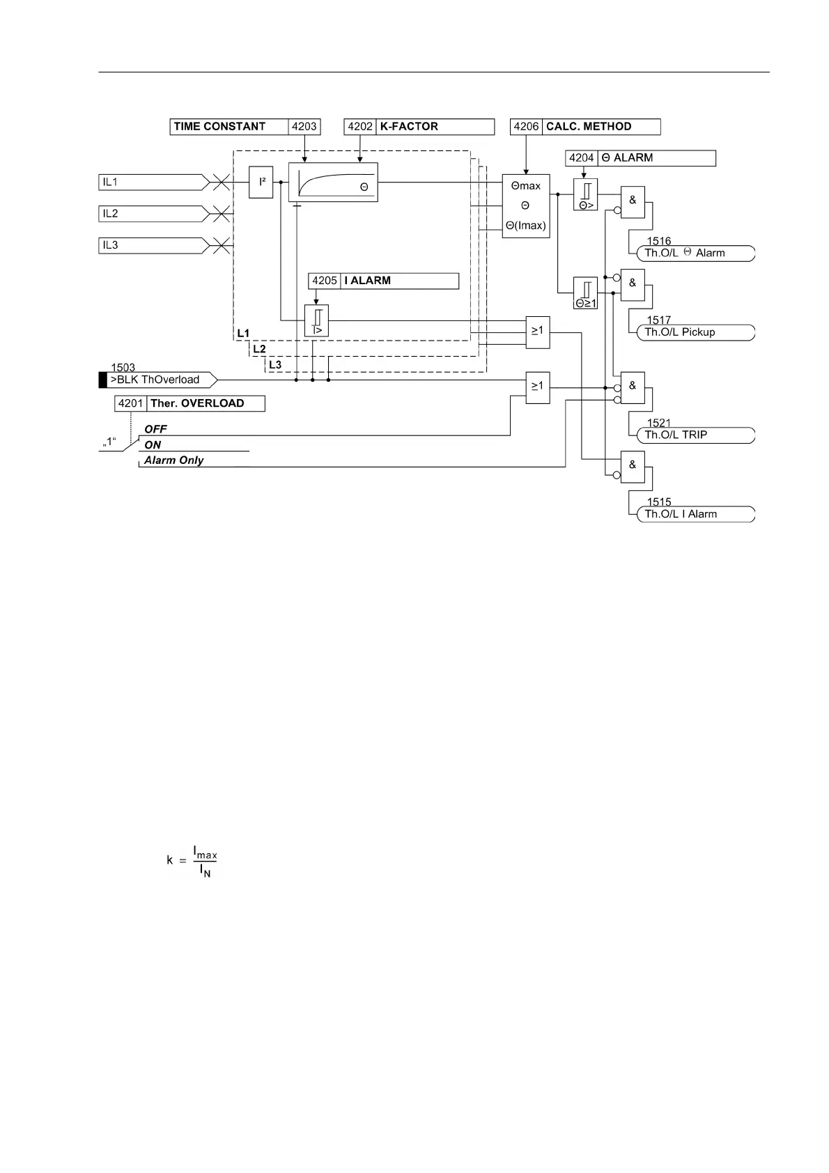
Figure 2-201 Logic diagram of the thermal overload protection
2.23.2 Setting Notes
General
A prerequisite for using the thermal overload protection is that during the configuration of the scope of functions
at address 142 Therm.Overload = Enabled was applied. At address 4201 Ther. OVERLOAD the function
can be turned ON or OFF. Furthermore, Alarm Only can be set. With the latter setting the protection function
is active but only outputs the indication „Th.O/L Pickup“ (address 1517) when the tripping temperature is
reached. The indication „Th.O/L TRIP“ (address 1521) is not generated.
k-factor
The nominal device current is taken as a basis for overload detection. The setting factor k is set under address
4202 K-FACTOR. It is determined by the relation between the permissible thermal continuous current and this
nominal current:
The permissible continuous current is at the same time the current at which the e-function of the overtemper-
ature has its asymptote. It is not necessary to determine the tripping temperature since it results automatically
from the final rise temperature at k · I
N
. Manufacturers of electrical machines usually state the permissible con-
tinuous current. If no data are available, k is set to 1.1 times the nominal current of the protected object. For
cables, the permissible continuous current depends on the cross section, the insulation material, the design
and the way they are laid, and can be derived from the relevant tables.
Please note that the overload capability of electrical equipment relates to its primary current. This has to be
considered if the primary current differs from the nominal current of the current transformers.

 Loading...