Mounting and Commissioning
3.1 Mounting and Connections
SIPROTEC, 7SD5, Manual
C53000-G1176-C169-5, Release date 02.2011
506
3.1.2.3 Switching Elements on Printed Circuit Boards
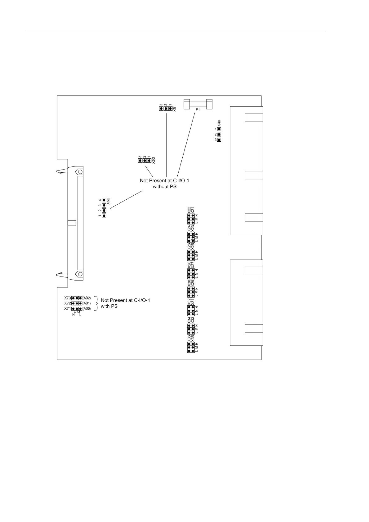
Input/output module C-I/O-1
Figure 3-5 Input/output board C-I/O-1 with representation of the jumpers required for checking the setting
The power supply is situated
• On the input/output board C-I/O-1 (No. 2 in Figure 3-3, slot 19) for housing size
1
/
2
,
• On the input/output board C-I/O-1 (No. 2 in Figure 3-4, slot 33 left) for housing size
1
/
1
,
The preset nominal voltage of the integrated power supply is checked according to Table 3-2, the quiescent
state of the life contact is checked according to Table 3-3.

 Loading...