Functions
2.2 Protection Data Interfaces and Protection Data Topology
SIPROTEC, 7SD5, Manual
C53000-G1176-C169-5, Release date 02.2011
84
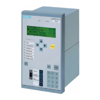
Figure 2-18 External button wiring for controlling the differential protection commissioning mode
Bu1 Button „Deactivating differential protection commissioning mode“
Bu2 Button „Activating differential protection commissioning mode“
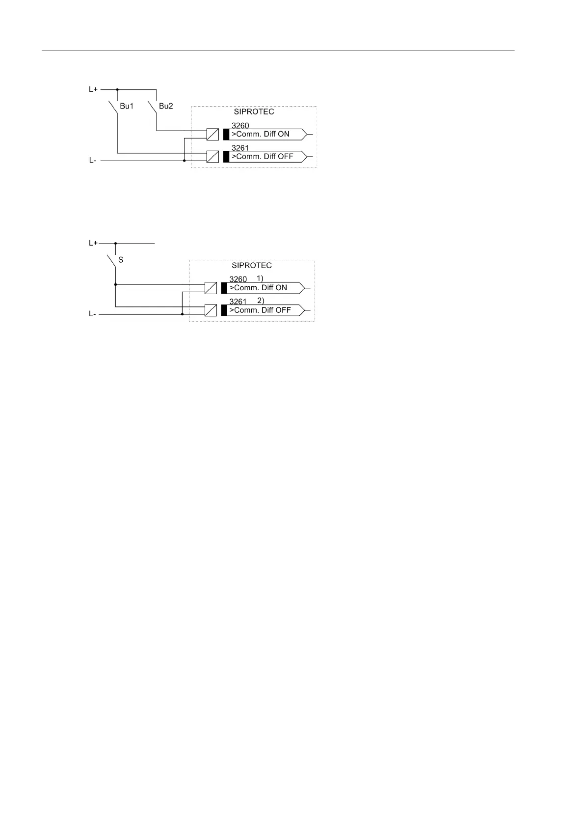
Figure 2-19 External switch wiring for controlling the differential protection commissioning mode
S Switch „Activating/deactivating differential protection commissioning mode“
1) Binary input as NO contact
2) Binary input as NC contact
2.2.3 Protection Data Interfaces
2.2.3.1 Setting Notes
General Information about Interfaces
The protection data interfaces connect the devices with the communication media. The communication is per-
manently monitored by the devices. Address 4509 T-DATA DISTURB defines after which delay time the user
is informed about a faulty or missing telegram. Address 4510 T-DATAFAIL is used to set the time after which
a transmission failure alarm is output. Address 4512 Td ResetRemote determines how long remote signals
remain standing after a communication disturbance.

 Loading...