Functions
2.2 Protection Data Interfaces and Protection Data Topology
SIPROTEC, 7SD5, Manual
C53000-G1176-C169-5, Release date 02.2011
90
2.2.4 Differential Protection Topology
2.2.4.1 Setting Notes
Protection data topology
First of all, define your protection data communication topology: Number the devices consecutively. This num-
bering is a serial device index
that serves for your own overview. It starts for each distance differential protection
system (i.e. for each protected object) with 1. For the differential protection system the device with index 1 is
always the absolute time master, i.e. the absolute time management of all devices which belong together
depends on the absolute time management of this device, if synchronization is set to Source or Timing
Master. As a result, the time information of all devices is comparable at all times. The Timing Master-Setting
has only influence on the absolut time (SCADA-Time). This setting has no impact on the differential protection.
The device index thus serves for the unique identification of the devices within a differential protection system
(i.e. for one protected object).
In addition, assign an ID number to each device (device-ID
). The device ID is used by the communication
system to identify each individual device. It must be between 1 and 65534 and must be unique within the com-
munication system. The ID number thus identifies the devices in the communication system (according to a
device address) since the exchange of information between several differential protection systems (thus also
for several protected objects) can be executed via the same communication system.
Please make sure that the possible communication connections and the existing interfaces are in accordance
with each other. If not all devices are equipped with two protection data interfaces, those with only one protec-
tion data interface must be located at the ends of the communication chain. A ring topology is only possible
if all devices in a differential protection system are equipped with two protection data interfaces.
If you work with different physical interfaces and communication links, please make sure that every protection
data interface corresponds to the projected communication link (direct FO or communication network).
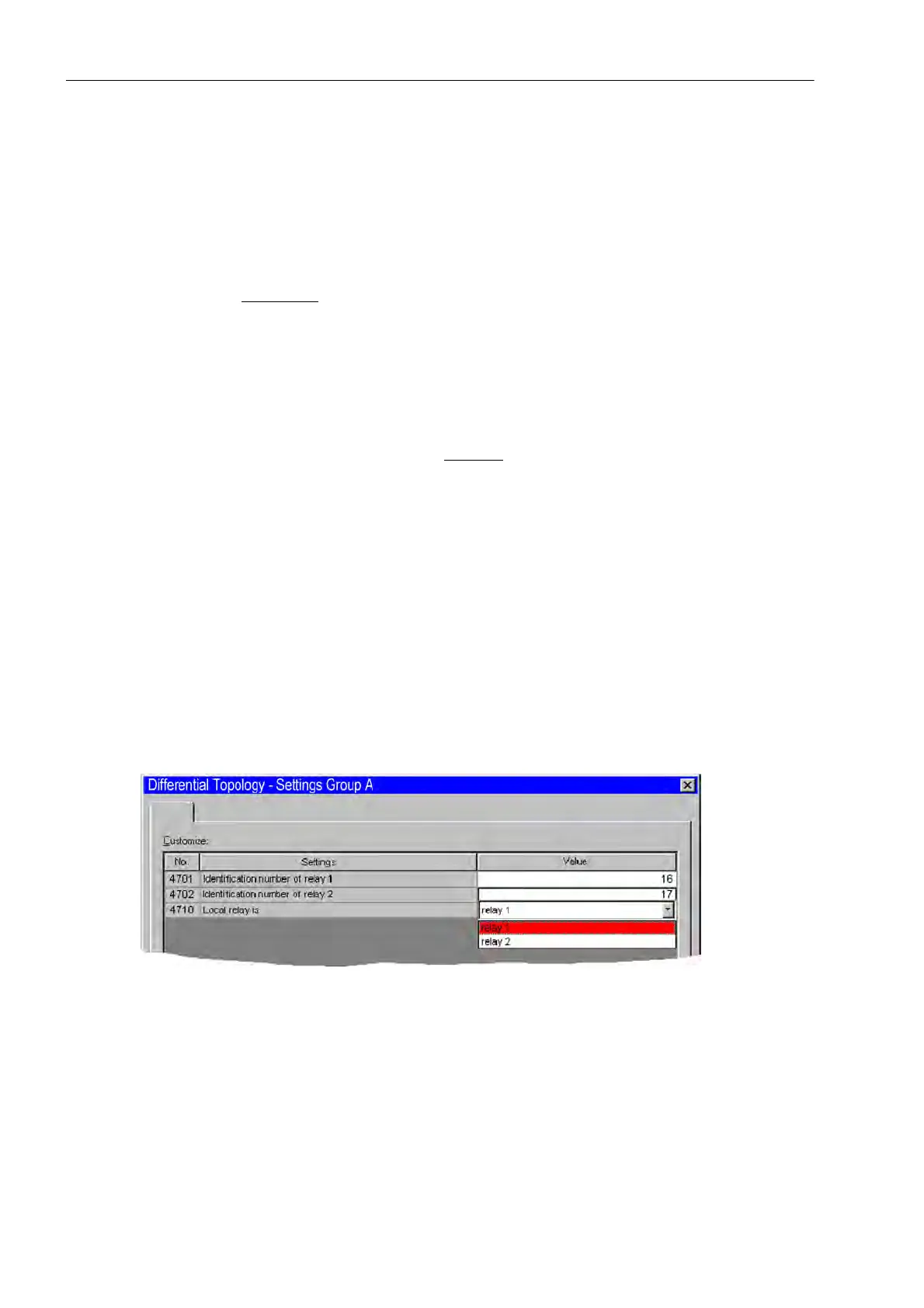
For a protected object with two ends (e.g. a line) the addresses 4701 ID OF RELAY 1 and 4702 ID OF
RELAY 2 are set, e.g. for device 1 the device-ID 16 and for device 2 the device-ID 17 (Figure 2-20). The indices
of the devices and the device-IDs do not have to match here, as mentioned above.
Figure 2-20 Differential protection topology for 2 ends with 2 devices — example
If more than two ends (and corresponding number of devices) are available, the further devices are assigned
to their device IDs with the parameter addresses 4703 ID OF RELAY 3, 4704 ID OF RELAY 4, 4705 ID
OF RELAY 5 and 4706 ID OF RELAY 6. A maximum of 6 line ends with 6 devices is possible. Figure 2-21
shows an example with 4 devices. During the configuration of the protection functions (Section 2.1.1.3), the
number of devices required for the relevant case of application was set in address 147 NUMBER OF RELAY.
Device IDs can be entered for as many devices as configured under that address, no further IDs are offered
during parameterization.

 Loading...