Functions
2.27 Command Processing
SIPROTEC, 7SD5, Manual
C53000-G1176-C169-5, Release date 02.2011
490
The display shows the configured interlocking reasons. The are marked by letters as explained in Table 2-26.
Table 2-26 Interlocking Commands
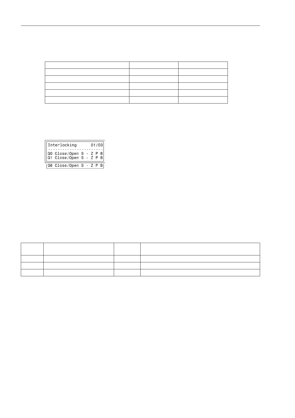
Figure 2-239 shows all interlocking conditions (which usually appear in the display of the device) for three
switchgear items with the relevant abbreviations explained in Table 2-26. All parameterised interlocking condi-
tions are indicated.
Figure 2-239 Example of configured interlocking conditions
Control Logic via CFC
For bay interlocking, a release logic can be created using CFC. Via specific release conditions the information
„released“ or „bay interlocked“ are available, e.g. object „Release CD Close“ and „Release CD Open“ with the
information values: ON / OFF).
2.27.1.4 Information List
Interlocking Commands Command Display
Switching Authority L L
System Interlocking S S
Bay Interlocking Z Z
SET = ACTUAL (switch direction check) P P
Protection Blockage B B
No. Information Type of In-
formation
Comments
- ModeREMOTE IntSP Controlmode REMOTE
- Cntrl Auth IntSP Control Authority
- ModeLOCAL IntSP Controlmode LOCAL

 Loading...