12 Hand Controls Service
Manual Lift Lever Service
12 - 8
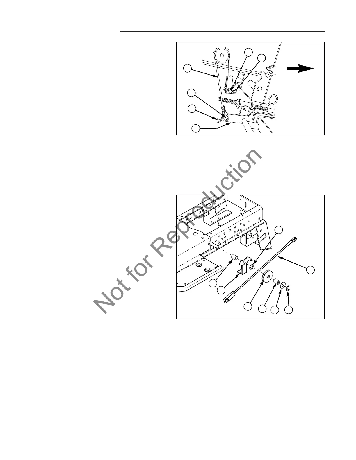
Lift Cable & Pulley Replacement
NOTE: The right side pulley is secured with a lockwasher
and nut instead of a C-clip.
IMPORTANT NOTE: For both lift cables, the mower cle-
vis pin (D) is installed from right to left; the tractor lift cle-
vis pin (B) is installed from left to right. The pins must be
installed in this orientation for proper clearance.
The right and left lift cable pulley assemblies are assem-
bled to the sides of the frame, and are accessible
through the rear wheel wells.
1. Detach the lift cable (C, Figure 3) from the mower
and lift lever arm.
2. Remove the c-clip (F, Figure 4), washer (E), and
spacer (D).
3. Slide the pulley out so that the cable clears the cable
guide. Or remove and replace the pulley.
4. Install in reverse order of removal. Orient the cable
as shown.
Figure 3. Mower Lift - 50” Manual Lift Models
A. Hair Pin Clip
B. Clevis Pin (Inserted Left to Right)
C. Lift Cable
D. Clevis Pin (Inserted Right to Left)
E. Hair Pin Clip & Washer
F. Mower Lift Arm
C
B
D
A
E
F
FRONT
A
B
H
C
D
E
F
G
Figure 4. Lift Cable Replacement
A. Spacer E. Washer, Large
B. Cable Guide F. C-Clip
C. Pulley G. Cable
D. Spacer H. Washer, Small
 Loading...