7 Electrical System Service
Linear Diagrams
7 - 10
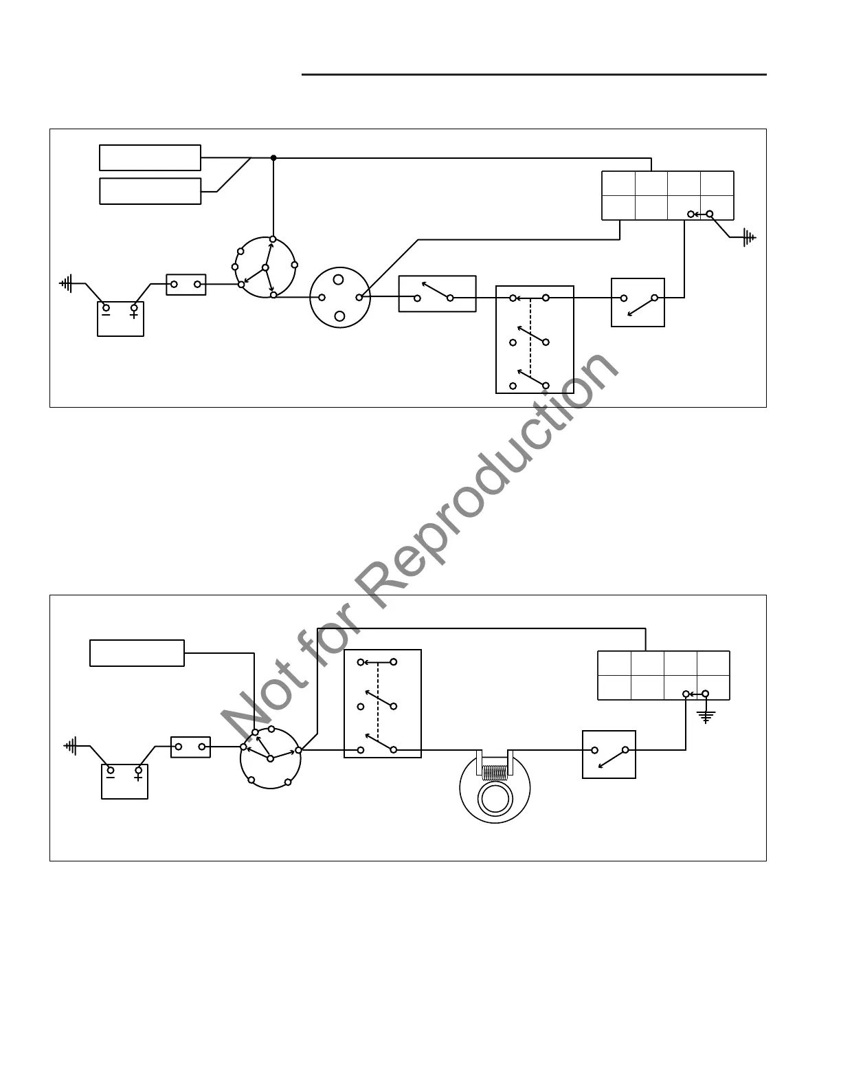
CRANKING CIRCUIT
The cranking circuit is only active when the ignition key
switch is in the start position.
Power is supplied through the circuit breaker to the B ter-
minal of the ignition switch. When the switch is turned to
the start position, contacts are closed between the B - L
terminals and B - S terminals of the ignition switch.
SOLENOID
B
S
87 65
12 34
N.O.
SEAT SWITCH
(UNOCCUPIED)
BATTERY
CIRCUIT
BREAKER
PTO SWITCH
(OFF POSITION)
N.O.
N.O. or N.C.
N.C .
PEDAL SWITCH
(w/ PEDAL UP)
N.O.
KEY SWITCH
(START POSITION)
A
M
L
G
B
S
FUEL SOLENOID
ACCESORIES
"D" SPLICE
Figure 4. Cranking Circuit Linear Diagram
The B - S connection applies power to the starter sole-
noid, safety switches, and #3 terminal of the interlock
module. If all controls are disengaged the safety switch-
es allow current to pass through to the #3 terminal of the
module grounding the solenoid, activating the starter.
The B - L connection supplies power to activate the mod-
ule and power the accessories.
LINEAR CIRCUIT DIAGRAMS
N.O.
SEAT SWITCH
(UNOCCUPIED)
BATTERY
CIRCUIT
BREAKER
A
M
L
G
B
S
PTO SWITCH
(OFF POSITION)
N.O.
N.O.
N.C .
KEY SWITCH
(RUN POSITION)
87 65
12 34
ELECTRIC PTO
CLUTCH
ALTERNATOR
Figure 5. PTO Circuit Linear Diagram
RUN POSITION
When the key is turned to the RUN position (after the
engine has started) the battery, alternator, fuel solenoid,
head lights, and PTO clutch are connected through the
key switch.
This multiple splice supplies alternator power to the bat-
tery for charging and to the rest of the tractor electrical
system to run the accessories and PTO clutch.
 Loading...