7 - 33
7 Electrical System Service
Component Tests
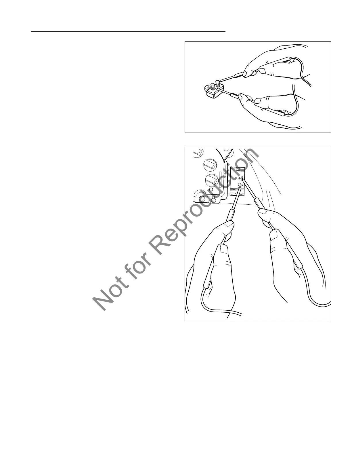
Figure 41. Testing Driving Light Switch
Figure 40. Testing Circuit Breaker
O. Circuit Breaker Test
All circuit breakers are located under the dashboard. The
circuit breaker resets itself automatically. If the circuit
doesn’t come back on, check it immediately. See Figure
40.
The circuit breaker is connected to one of the small sole-
noid posts along with the positive battery cable.
1. Set the VOM to VDC.
2. With the negative probe, touch ground.
3. Touch the positive probe to one post of the circuit
breaker, and then the other. Both posts should have
close to full battery voltage going to them. If not,
replace the breaker.
4. Set VOM to Ohm.
5. Disconnect the circuit breaker leads and probe both
circuit breaker terminals. If the VOM reads 5 ohm or
more, replace the circuit breaker.
S. Voltage Regulator
The voltage regulator is part of the engine, refer to the
engine manufacturer’s operators manual for information
relating to engine components. On some alternators the
voltage regulator is built in.
P. PTO Clutch
Refer to PTO CLUTCH SERVICE section, for compete
PTO clutch testing information and replacement proce-
dures.
Q. Headlight Switch Test
1. If needed, remove the switch from the dashboard.
2. Set the VOM to Ohm.
3. With the switch in the OFF position, probe both termi-
nals (Figure 34). The VOM should read no continuity.
4. Turn the switch to ON. The VOM should read conti-
nuity.
R. Fuel Solenoid Test
Refer to the engine manufacturer’s operators manual for
information relating to engine components.
1. Turn the ignition switch from OFF to RUN. There
should be an audible “click” as the shut-off solenoid
opens.
If there is no “click” use a VOM set to VDC. Test the
voltage between the solenoid lead and ground. With
the ignition switch in the RUN position, the lead
should have 12 volts. If not, check the ignition switch
and wiring.
If the solenoid is receiving 12 VDC and is not open-
ing, replace the solenoid.
T. Alternator
Refer to the engine manufacturer’s operators manual for
information relating to engine components.
 Loading...