7 - 26
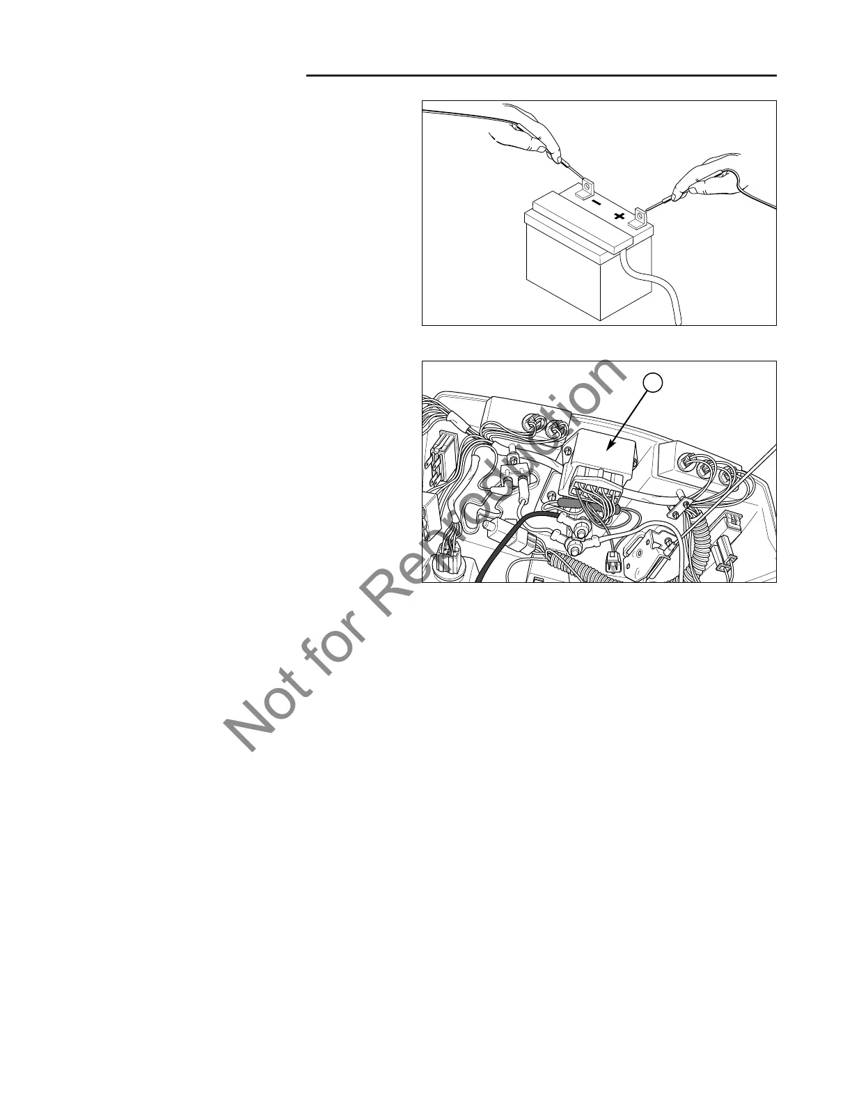
Figure 24. Check Battery Voltage
Figure 25. Interlock Module
A. Interlock Module
D. Isolated Battery Voltage Check
See Figure 24.
In some cases, a short in the wiring or another compo-
nent could be causing a low level current draw on the
battery. This would be indicated by a slow drain on the
battery during times when the engine is off. The easiest
way to check this is to check the voltage with the battery
installed, and then with the battery uninstalled (isolated).
Then reconnect the battery terminals with an amp meter
in series with the battery and terminal. There should be
no current draw off the battery when all accessories are
off and the ignition key switch is in the OFF position.
E. Charging Voltage Check
To determine if the charging system is functioning prop-
erly, check the battery voltage while the engine is run-
ning. The charging system produces a slightly higher
voltage than the battery so that the battery will recharge
and there is enough energy remaining to supply power to
the electrical systems.
F. Interlock Module
Due to the complex circuitry and sensitivity of the electri-
cal components that make up the interlock module, it
cannot be feasible be tested. Test the switches, wires,
and connections in the rest of the electrical system, then
replace the module as a last resort. Bear in mind that a
module failure may be caused by another malfunctioning
electrical component. Therefore it is critical that the rest
of the electrical system be checked.
7 Electrical System Service
Component Tests
G. Ignition Switch Tests
To perform these tests, the ignition switch needs to be
removed from the dashboard.
TEST START POSITION
NOTE: To perform this test, the ignition key switch may
need to be placed in a vice to hold the switch.
See Figure 26.
1. Set VOM to Ohm.
2. Turn the key to the START position and hold it there
for the following steps.
3. Connect test leads to terminals B and L of the ignition
key switch. The test meter should show continuity.
4. Connect test leads to terminals B and S of the igni-
tion key switch. The test meter should show continu-
ity
5. Connect test leads to terminals L and S of the ignition
key switch. The test meter should show continuity.
A
6. Turn the key switch to the OFF position and repeat
steps 3, 4, and 5. With the key in the OFF position,
the combinations listed above should show no conti-
nuity.
 Loading...